Voltage Sensor Module interface
with Arduino, Node MCU, ESP32 and LCD display
A voltage sensor is a sensor used to calculate and monitor the amount of voltage in an object. Voltage sensors can determine the AC voltage or DC voltage level. The input of this sensor is the voltage, whereas the output is the switches, Analog voltage signal, a current signal, or an audible signal.
Sensors are devices that can sense or identify and react to certain types of electrical or optical signals. The implementation of a voltage sensor and current sensor techniques have become an excellent choice for the conventional current and voltage measurement methods.
It can measure the AC level and/or DC voltage level. The input to the voltage sensor is the voltage itself, and the output can be Analog voltage signals, switches, audible signals, analog current levels, frequency, or even frequency-modulated outputs.
That is, some voltage sensors can provide sine or pulse trains as output, and others can produce amplitude modulation, pulse width modulation, or frequency modulation outputs.


In voltage sensors, the measurement is based on a voltage divider. Two main types of voltage sensors are available: capacitive type voltage sensor and resistive type voltage sensor.
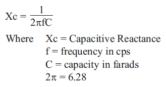
voltage division in two capacitors which are in series. Usually, in series circuits, high voltage will develop across the component with high impedance. In the case of capacitors, capacitance and impedance (capacitive reactance) are always inversely proportional.


The relation between voltage and capacitance is V=Q/C where Q =Charge (Coulomb)
From the above two relations, we can clearly state that the highest voltage will accumulate across the smallest capacitor. The capacitor voltage sensors work based on this simple principle. Consider we are holding the sensor and then placing its tip near a live conductor.
Voltage Sensor is a precise low-cost sensor for measuring voltage. It is based on the principle of resistive voltage divider design. It can make the red terminal connector input voltage to 5 times smaller.
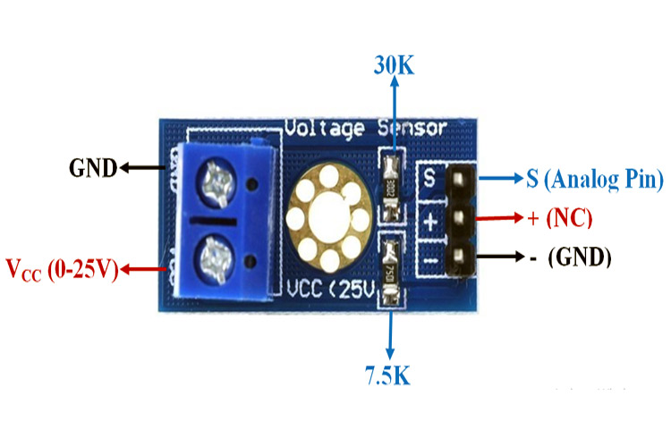
Voltage Sensor Module Pinout Configuration
Voltage Detection Sensor Module Features & Specifications
Input Voltage: 0 to 25V
Voltage Detection Range: 0.02445 to 25
Analog Voltage Resolution: 0.00489V
Needs no external components
Voltage Detection Sensor Module is a simple and very useful module that uses a potential divider to reduce any input voltage by a factor of 5. This allows us to use the Analog input pin of a microcontroller to monitor voltages higher
than it capable of sensing. For example, with a 0V – 5V Analog input range, you are able to measure a voltage up to 25V. This module also includes convenient screw terminals for easy and secure connections of a wire.
Pin Name |
Description |
|---|---|
|
VCC |
Positive terminal of the External voltage source (0-25V) |
|
GND |
Negative terminal of the External voltage source |
|
S |
Analog pin connected to Analog pin of Arduino |
|
+ |
Not Connected |
|
- |
Ground Pin connected to GND of Arduino |
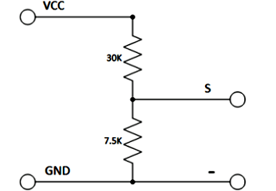
The internal circuit diagram of the Voltage Sensor Module is given below.
The voltage circuit consists of a voltage divider circuit of two resistors in which R1 is 30K and R2 is 7.5K.
Interfacing a voltage sensor with Arduino or any other microcontroller is pretty straight forward. Connect the VCC and GND of voltage source whose voltage to be measured to the screw terminals of the voltage sensor. Connect the S and – (GND) pins of voltage sensor to Analog pin and GND of Arduino respectively.
Input and output voltage can be calculated using:
Vin = Vout * (R2/(R1+R2)) Here R1 = 30K ohm and R2 = 7.5K ohm
Vout = (analogvalue * 5 / 1024).
