TEMT6000 Ambient Light Sensor
with Arduino, Node MCU, ESP32
TEMT6000 Ambient Light Sensor measures illuminance. The Illuminance is a measure of the total quantity of visible light emitted by a source. It is referred to as luminous flux and measured in lumens (lm) per meter square.

But the question is why does the TEMT6000 measure illuminance only? The answer is measuring the intensity of light without factoring in distance is very difficult. For example, if you have a bright source far away and a dim source very close, they can appear to have the same brightness. This is because the brighter source’s light will have to dissipate over a larger volume compared to the lesser bright light. This is why the sensor will read a smaller value if you move the same source of light farther away from it, essentially increasing the amount of space that the same amount of light has to fill between the source and the sensor.

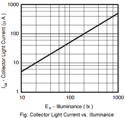
Here is a graphical relationship between the current (in µA) and illuminance of the immediate vicinity perceived by the sensor:
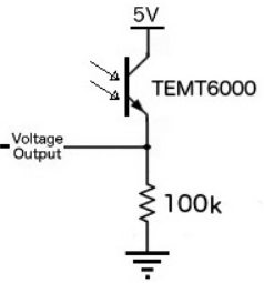
The ambient light sensor used is the TEMT6000. This sensor acts as an NPN transistor, so the more the sensor is exposed to light, the stronger the base bias, thus the higher the Analog voltage on the signal pin. Being a phototransistor, this sensor acts just like any other NPN transistor — the greater the incoming light on the Base, the the more current that can flow from the Collector to the Emitter. Only light that falls within the visible spectrum (390–700 nm) will alter the Base. A voltage divider circuit is used to create a usable signal from the light sensor for a microcontroller.
As we know, most of the modern devices which use Light sensors are notably used for auto-brightness according to light intensity. The device includes mobile phone screens and digital cameras for adjusting exposure. So here we will use one of the best light sensors, TEMT6000 Ambient Light Sensor and interface it with Arduino to measure the light intensity.
We will discuss here the TEMT6000 Ambient Light Sensor and understand the concept of working of the light sensor. They will detect the brightness of its surroundings. The sensor can also be used in Spectrometer for Triad Spectroscopy.

With the Ambient Light Sensor Breakout, it is easy to interface TEMT6000 Light Sensor to detect light levels. TEMT6000 Light Sensor will detect the brightness of its surroundings. While there are many properties of light that can help us categorize its brightness, the TEMT6000 measures illuminance (measured in lux (lx), often denoted Ev). TEMT6000 is very intuitive to use: brighter = more current, darker = less current.
The voltage coming from the voltage divider circuit, is connected to A0 an Analog to Digital Converter (ADC) of Arduino.
Only light that falls within the visible spectrum (390–700 nm) will alter the Base. Infrared, ultraviolet, or any other light we can’t directly see will have no effect on the sensor. We will interface the TEMT6000 sensor with Arduino & Arduino will be interfaced with 16×2 LCD Display. The light intensity will be measured in terms of percentage and will be displayed on LCD Display.
TEMT6000 Ambient Light Sensor with Arduino:
TEMT6000 Ambient Light Sensor has 3 Pins of which VCC and GND are connected to 5 volts and ground of Arduino. The Signal out of module is connected to A0 of Arduino.
Apart from this we need to connect two LEDs and one Buzzer into Arduino circuit to give us critical information. Green LED is connected to Pin 2 of the Arduino which turns on whenever the Arduino is switched on to indicate power on. The Red LED and Buzzer is connected to Pin 3 and Pin 4 of Arduino. Both will turn on whenever the Pin A0 level is above the set value of Ambient light intensity.
TEMT6000 Ambient Light Sensor with Node MCU:
TEMT6000 Ambient Light Sensor has 3 Pins of which VCC and GND are connected to 3.3 volts and ground of Node MCU. The Signal out of module is connected to ADC0 of Node MCU. Apart from this we need to connect two LEDs and one Buzzer into Node MCU circuit to give us critical information. Green LED is connected to Pin GPIO2 of the Node MCU which turns on whenever the Node MCU is switched on to indicate power on. The Red LED and Buzzer is connected to Pin GPIO3 and Pin GPIO4 of Node MCU. Both will turn on whenever the Pin ADC0 level is above the set value of Ambient light intensity.
TEMT6000 Ambient Light Sensor with ESP32:
TEMT6000 Ambient Light Sensor has 3 Pins of which VCC and GND are connected to 3.3 volts and ground of ESP32. The Signal out of module is connected to ADC0 of ESP32. Apart from this we need to connect two LEDs and one Buzzer into ESP32 circuit to give us critical information. Green LED is connected to Pin GPIO2 of the ESP32 which turns on whenever the ESP32 is switched on to indicate power on. The Red LED and Buzzer is connected to Pin GPIO3 and Pin GPIO4 of ESP32. Both will turn on whenever the Pin ADC0 level is above the set value of Ambient light intensity.
