RCWL-0516 Microwave Radar Motion Sensor Interfacing
with Arduino, Node MCU, ESP32
For security reasons and also to save power we use every day Passive Infrared sensor which is economically priced and provides reasonable amount of flexibility. But since it is dependent on body heat for triggering the alarm or switching on LED bulb it does not deliver consistent and reliable solution. For many applications when we need the light to be on till the presence of people or person in the room, after pre-set time the light goes off. This has led to invention of RCWL-0516 microwave radar motion sensor based on doppler effect.
The Doppler effect, named after the Austrian physicist Christian Doppler who proposed it in 1842, describes the change in frequency observed by a stationary observer when the source of the frequency is moving. This holds true for all sorts of waves, such as water, light, radio, and sound.
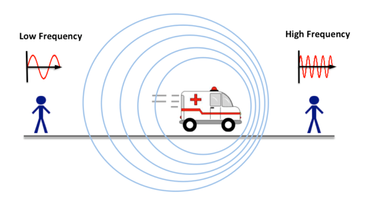
When a wave source is moving relative to an observer, there will be a change in the observed frequency and wavelength. This is known as the Doppler effect, and a good example which demonstrates this is the change in the sound of an ambulance’s siren as it approaches and moves past you. As shown in the diagram, as the ambulance travels towards you the frequency of the waves is increased and the sound will be higher in pitch. Once the ambulance has passed you and is travelling away, the frequency of the waves decreases and the sound is lower in pitch.
RCWL-0516 has Doppler radar which works by bouncing a microwave signal off a desired target and reading the frequency of the returned signal. By analysing how the target’s motion has altered the frequency of the transmitted signal, the target’s velocity can be measured.
The RCWL-0516 is an active sensor, not a passive one like the HC-SR501 Passive Infrared (PIR). It sends out microwaves at a frequency of about 3.18 GHz and measures the radiation that is reflected back.
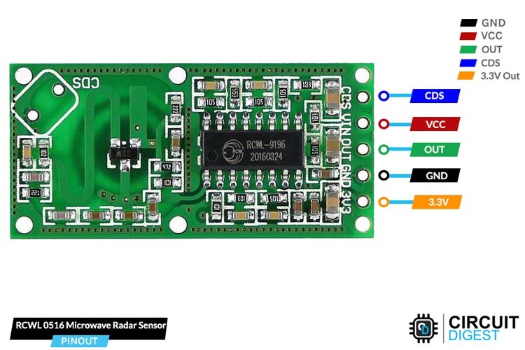
The RCWL-0516 itself is pretty straightforward and works out of the box. Simply apply power by connecting 5Volts to VCC and GND of Arduino to ground GND of RCWL-0516. The sensor output goes HIGH for two seconds when motion is detected and goes LOW when idle (no motion detected).
And the best part is that it can detect motion up to 7 meters away while only consuming less than 3 mA of current.
The RCWL-0516 also supports repeat triggers and has a 360-degree detection area without blind spots. Because the microwave antenna is integrated on the PCB itself, the RCWL-0516 has become a completely self-contained unit.
The RCWL-0516 also has support for an optional light-dependent resistor (LDR), which enables the device to operate only in the dark. This is useful for building motion-sensitive lighting systems.
There are LDR pads marked as CDS on the PCB which stands for cadmium sulphide which is used in LDRs. So we can solder LDR at this place or one of the output pin is marked as CDS and we can solder LDR between this pin and ground.
Apart from this there are three jumpers provided viz.,
C-TM (Pulse length Adjustment) – using this pulse length can be increased from 2 seconds to 50 seconds.
R-GN (Detection Range Adjustment) – The range can be reduced from 7 meters up to 1.5 meters.
R-CDS (Light Sensitivity Adjustment) – This can be used when LDR is not used.
This board operates at any voltage between 4 volts to 28 volts. There is 3.3 volts output pin which can be used by us for operating any relay etc.,
RCWL-0516 Microwave Radar Motion Sensor Interfacing with Arduino:
There are 5 Pins on RCWL-0516 board. VCC and GND are connected to 5 volts DC and ground pin of Arduino. Digital Out is connected to Pin 7 of Arduino. Whenever Pin 7 changes the status on detecting of movement, the Arduino would activate pin 12 which switches on the relay. The relay is connected to bulb and hence when there is movement the bulb will light.
There are two LEDs and a buzzer connected give certain indications. Green LED connected to Pin 2 of Arduino will light when Arduino is switched on to indicate Power on. Red LED and buzzer will turn on there is motion sensed. Red LED pin and buzzer are connected to Pin 3 and pin 4 of Arduino respectively.
RCWL-0516 Microwave Radar Motion Sensor Interfacing with Node MCU
There are 5 Pins on RCWL-0516 board. VCC and GND are connected to 3.3 volts DC and ground pin of Node MCU. Digital Out is connected to Pin GPIO7 of Node MCU. Whenever Pin GPIO7 changes the status on detecting of movement, the Node MCU would activate pin GPIO12 which switches on the relay. The relay is connected to bulb and hence when there is movement the bulb will light.
There are two LEDs and a buzzer connected give certain indications. Green LED connected to Pin GPIO2 of Node MCU will light when Node MCU is switched on to indicate Power on. Red LED and buzzer will turn on there is motion sensed. Red LED pin and buzzer are connected to Pin GPIO3 and pin GPIO4 of Node MCU respectively.
RCWL-0516 Microwave Radar Motion Sensor Interfacing with ESP32
There are 5 Pins on RCWL-0516 board. VCC and GND are connected to 3.3 volts DC and ground pin of ESP32. Digital Out is connected to Pin GPIO7 of ESP32. Whenever Pin GPIO7 changes the status on detecting of movement, the ESP32 would activate pin GPIO12 which switches on the relay. The relay is connected to bulb and hence when there is movement the bulb will light. There are two LEDs and a buzzer connected give certain indications. Green LED connected to Pin GPIO2 of ESP32 will light when ESP32 is switched on to indicate Power on. Red LED and buzzer will turn on there is motion sensed. Red LED pin and buzzer are connected to Pin GPIO3 and pin GPIO4 of ESP32 respectively.