Photo Interrupter interfacing to an Arduino,
Node MCU, ESP32
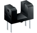
A Photo-interrupter is a transmission-type photosensor, which typically consists of a light emitting element and light receiving element aligned facing each other in a single package, that works by detecting light blockage when a target object comes between both elements, acting as an optical switch.

Unlike mechanical switches, photo-interrupters are non-contact (optical) switches, improving reliability by preventing wear-and-tear due to abrasion (contact). Current flows to the LED, causing it to light up. This light enters the phototransistor, resulting in current flow. Object detection is enabled by detecting the change in transistor current due to the presence/absence of a screen.
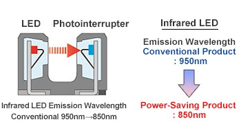
By bringing the receiving sensitivity characteristics of the phototransistor close to the IrLED emission wavelength, a power-saving photo interrupter that eliminates the wavelength difference loss component is achieved.
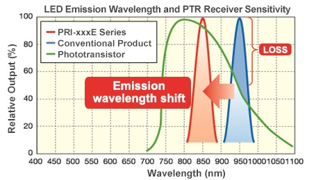
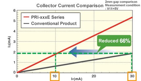
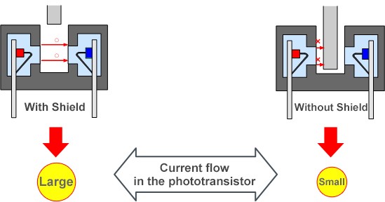
Photo Interrupter Sensor is a light occlusion interrupt sensor, which is often used in smart car speed measurement.
Principle: This product adopts a WYC-H206 slot photoelectric sensor, one end is an infrared transmitting tube, and the other end is an infrared receiving. When there is a block, the infrared receiving end cannot receive infrared and outputs a high level, which is triggered by inverting Schmitt. The device becomes low-level output, and the signal lamp is on at the same time. The use of the Schmitt trigger makes the output signal more stable, with good waveform and no jitter.
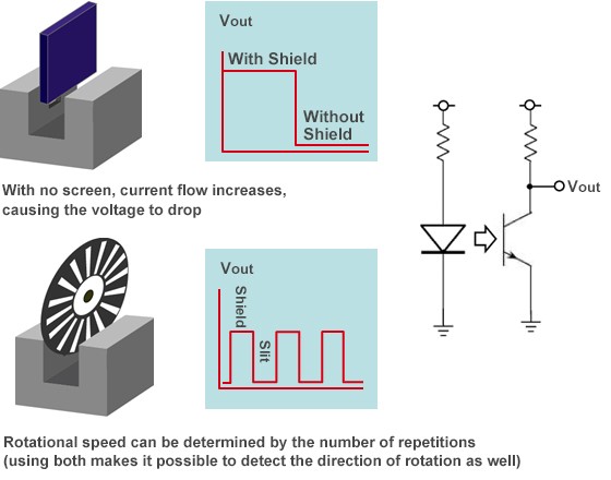
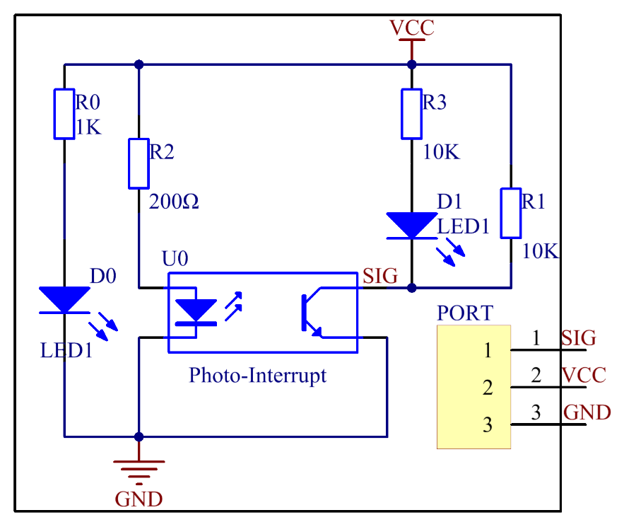
Usage Example: Detecting Voltage Change at the Phototransistor Side
A photo-interrupter is a sensor with a light-emitting component and light-receiving component packaged face to face. It applies the principle that light is interrupted when an object passes through the sensor. Therefore, photo-interrupters are widely used in speed measurement.
Basically, a photo-interrupter consists of two parts: transmitter and receiver. The transmitter (e.g., an LED or a laser) emits light and then the light goes to the receiver. If the light beam between the transmitter and receiver is interrupted by an obstacle, the receiver will detect no incident light even for a moment and the output level will change. In this experiment, we will turn an LED on or off by using this change.
Photo Interrupter interfacing to Arduino:
Photo Interrupter has 3 pins of which VCC & GND are connected to 5 volts DC and ground of Arduino. SIG or signal out is connected to Pin 7 of the Arduino which will trigger Pin 9 which could be connected to any action desired. Pin 7 will also trigger Pin 3 and Pin 4. Pin 3 is connected to Red LED buzzer is connected to Pin 4 to alert the interruption. Pin 2 is connected to Green LED which will switch on to indicate the power on of Arduino.
Photo Interrupter interfacing to Node MCU:
Photo Interrupter has 3 pins of which VCC & GND are connected to 3.3 volts DC and ground of Node MCU. SIG or signal out is connected to Pin GPIO7 of the Node MCU which will trigger Pin GPIO9 which could be connected to any action desired. Pin GPIO7 will also trigger Pin GPIO3 and Pin GPIO4. Pin GPIO3 is connected to Red LED buzzer is connected to Pin GPIO4 to alert the interruption. Pin GPIO2 is connected to Green LED which will switch on to indicate the power on of Node MCU.
Photo Interrupter interfacing to ESP32:
Photo Interrupter has 3 pins of which VCC & GND are connected to 3.3 volts DC and ground of ESP32. SIG or signal out is connected to Pin GPIO7 of the ESP32 which will trigger Pin GPIO9 which could be connected to any action desired. Pin GPIO7 will also trigger Pin GPIO3 and Pin GPIO4. Pin GPIO3 is connected to Red LED buzzer is connected to Pin GPIO4 to alert the interruption. Pin GPIO2 is connected to Green LED which will switch on to indicate the power on of ESP32.
