MQ-4 Methane CNG Gas Sensor Interfacing
with Arduino, Node MCU, ESP32
Working principle of Oxide based gas sensors: Tin oxide SnO2-based gas sensors have been widely used for detecting typical fault characteristic gases extracted from power transformer oil, namely, H2, CO, CO2, CH4, C2H2, C2H4, and C2H6, due to the remarkable advantages of high sensitivity, fast response, long-term stability, and so on.
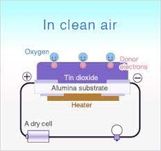
Gas sensing layer: It is the main component in the sensor which can be used to sense the variation in the concentration of the gases and generate the change in electrical resistance. The gas sensing layer is basically a chemiresistor which changes its resistance value based on the concentration of particular gas in the environment. Here the sensing element is made up of a Tin Dioxide (SnO2) which is, in general, has excess electrons (donor element). So whenever toxic gases are being detected the resistance of the element changes and the current flows through it varies which represents the change in concentration of the gases.
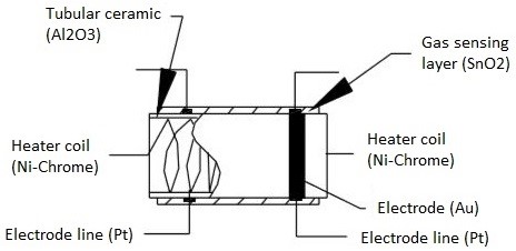
Heater coil: The purpose of the heater coil is to burn-in the sensing element so that the sensitivity and efficiency of the sensing element increases. It is made of Nickel-Chromium which has a high melting point so that it can stay heated up without getting melted.
Electrode line: As the sensing element produces a very small current when the gas is detected it is more important to maintain the efficiency of carrying those small currents. So Platinum wires come into play where it helps in moving the electrons efficiently.

Electrode: It is a junction where the output of the sensing layer is connected to the Electrode line. So that the output current can flow to the required terminal. An electrode here is made of Gold (Au –Aurum) which is a very good conductor.
Tubular ceramic: In between the Heater coil and Gas sensing layer, the tubular ceramic exists which is made of Aluminum oxide (Al2O3). As it has high melting point, it helps in maintaining the burn-in (preheating) of the sensing layer which gives the high sensitivity for the sensing layer to get efficient output current.
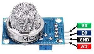
Mesh over the sensing element: In order to protect the sensing elements and the setup, a metal mesh is used over it, which is also used to avoid/hold the dust particles entering into the mesh and prevent damaging the gas sensing layer from corrosive particles.
SnO2 has become a novel material for gas sensors because its resistance changes due to the barrier changes before and after the gas molecules adsorption. Therefore, the performance of the materials used as gas sensors can be changed using doping.
Apart from Tin Oxide other oxides such as zinc oxides, titanium dioxide, iron oxides, cobalt oxide, tungsten trioxide and nickel oxide are used widely. The ideal operating temperature was found to be relatively low, at 250 °C which could be achieved by connecting to the heating element 5 Volts DC operating voltage of Arduino UNO.
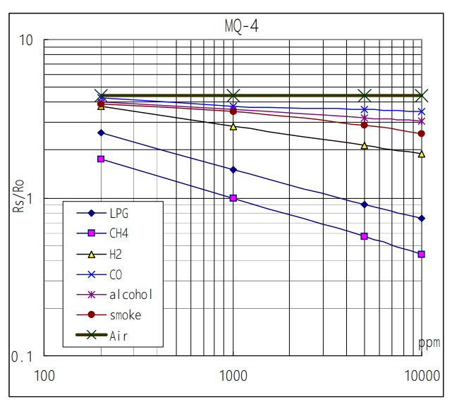
The MQ-4 Methane CNG Gas Sensor can detect Methane, CNG Gas in the air. MQ name is from Metal Oxide Semiconductor (MOS) type Gas Sensor. It is also known as Chemiresistors since the detection is dependent on a change in the sensing material’s resistance when the Gas comes into contact with it. How to Measure Gas Concentration in PPM using the MQ-4 Sensor? This is a very accurate sensor that is calibrated to detect the PPM of combustible gas present in the environment; but, in order to do so, you must first understand the MQ-4 Sensor’s sensitivity characteristics,
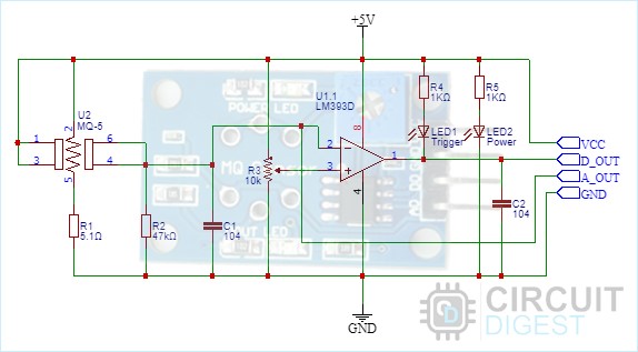
In the schematic, we have an LM393 op-amp, which is a low-power, low-offset voltage op-amp that can be driven by a +5V supply. The circuit cannot be powered using 3.3V since the MQ-4 Sensor’s minimum working voltage is 5V. The function of this op-amp is to convert an input Analog signal to a digital signal. Gas Sensor module has an integrated 10K potentiometer for adjusting the sensitivity of the triggering voltage.
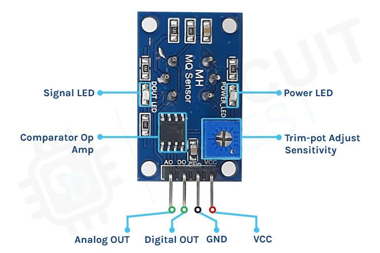
Apart from that, two LEDs are present. The first is the power LED, and the second is the trigger LED. The power LED lights when the board is powered up. The trigger LED lights when a predefined threshold is reached. Finally, the board has two decoupling capacitors that aid to reduce noise. The substrate composed of nichrome wire gets heated up and releases tin oxide from platinum wire coated with a tin dioxide covering which when comes in contact with combustible gas under test, the resistance and consequently comparator op amp voltage changes making the sensor to deliver Analog output as well as Digital output.
Let us look at the Pin configuration of MQ-4 Methane CNG Gas Sensor
MQ-4 Methane CNG Gas Sensor Interfacing with Arduino:
VCC & GND Pins of MQ-4 Methane CNG Sensor is connected to 5 Volts DC and ground Pin of Arduino. Digital OUT is connected to Pin 7 of Arduino which when triggered Arduino will pull Pin 9 high for downstream action. Analog OUT is connected to A0 Analog port of Arduino A to D Converter. The output of which could be displayed on LCD or OLED. Then there are two LEDs and one Buzzer to be connected to Pin 2, Pin 3 and Pin 4. Green LED connected to Pin 2 will light up when Arduino is powered up. Red LED connected to Pin 3 and Buzzer connected to Pin 4 will be on when Pin 7 gets activated.
MQ-4 Methane CNG Gas Sensor Interfacing with Node MCU:
VCC & GND Pins of MQ-4 Methane CNG Sensor is connected to 3.3 Volts DC and ground Pin of Node MCU. Digital OUT is connected to Pin GPIO7 of Node MCU which when triggered Node MCU will pull Pin GPIO9 high for downstream action. Analog OUT is connected to ADC0 Analog port of Node MCU A to D Converter. The output of which could be displayed on LCD or OLED. Then there are two LEDs and one Buzzer to be connected to Pin GPIO2, Pin GPIO3 and Pin GPIO4. Green LED connected to Pin GPIO2 will light up when Node MCU is powered up. Red LED connected to Pin GPIO3 and Buzzer connected to Pin GPIO4 will be on when Pin GPIO7 gets activated.
MQ-4 Methane CNG Gas Sensor Interfacing with ESP32:
VCC & GND Pins of MQ-4 Methane CNG Sensor is connected to 3.3 Volts DC and ground Pin of ESP32. Digital OUT is connected to Pin GPIO7 of ESP32 which when triggered Node MCU will pull Pin GPIO9 high for downstream action. Analog OUT is connected to ADC0 Analog port of ESP32 A to D Converter. The output of which could be displayed on LCD or OLED. Then there are two LEDs and one Buzzer to be connected to Pin GPIO2, Pin GPIO3 and Pin GPIO4. Green LED connected to Pin GPIO2 will light up when ESP32 is powered up. Red LED connected to Pin GPIO3 and Buzzer connected to Pin GPIO4 will be on when Pin GPIO7 gets activated.