Microphone Sound Sensor interfacing
with Arduino, Node MCU, ESP32

Microphones are transducers which detect sound signals and produce an electrical image of the sound, i.e., they produce a voltage or a current which is proportional to the sound signal. The most common microphones for musical use are dynamic, ribbon, or condenser microphones. Besides the variety of basic mechanisms, microphones can be designed with different directional patterns and different impedances.
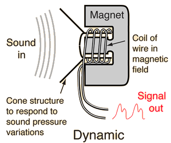
Dynamic Microphones Principle: sound moves the cone and the attached coil of wire moves in the field of a magnet. The generator effect produces a voltage which “images” the sound pressure variation – characterized as a pressure microphone.

Advantages:
Relatively cheap and rugged.
Can be easily miniaturized.
Disadvantages:
The uniformity of response to different frequencies does not match that of the ribbon or condenser microphones.
The geometry of a dynamic microphone is like that of a tiny loudspeaker, and that is not just a coincidence. A dynamic microphone is essentially the inverse of a dynamic loudspeaker. In a dynamic microphone, the sound pressure variations move the cone, which moves the attached coil of wire in a magnetic field, which generates a voltage. In the loudspeaker, the inverse happens: the electric current associated with the electrical image of the sound is driven through the coil in the magnetic field, generating a force on that coil. The coil moves in response to the audio signal, moving the cone and producing sound in the air.


Condenser Microphones
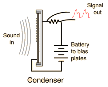
Principle: sound pressure changes the spacing between a thin metallic membrane and the stationary back plate. The plates are charged to a total charge
where C is the capacitance, V the voltage of the biasing battery, A the area of each plate and d the separation of the plates.
Advantages: Best overall frequency response makes this the microphone of choice for many recording applications.
Disadvantages: Expensive, May pop and crack when close miked, Requires a battery or external power supply to bias the plates.
A change in plate spacing will cause a change in charge Q and force a current through resistance R. This current “images” the sound pressure, making this a “pressure” microphone.
The Microphone Sound Sensor
The microphone sound sensor, as the name says, detects sound. It gives a measurement of how loud a sound is.
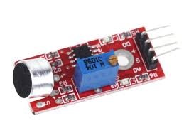
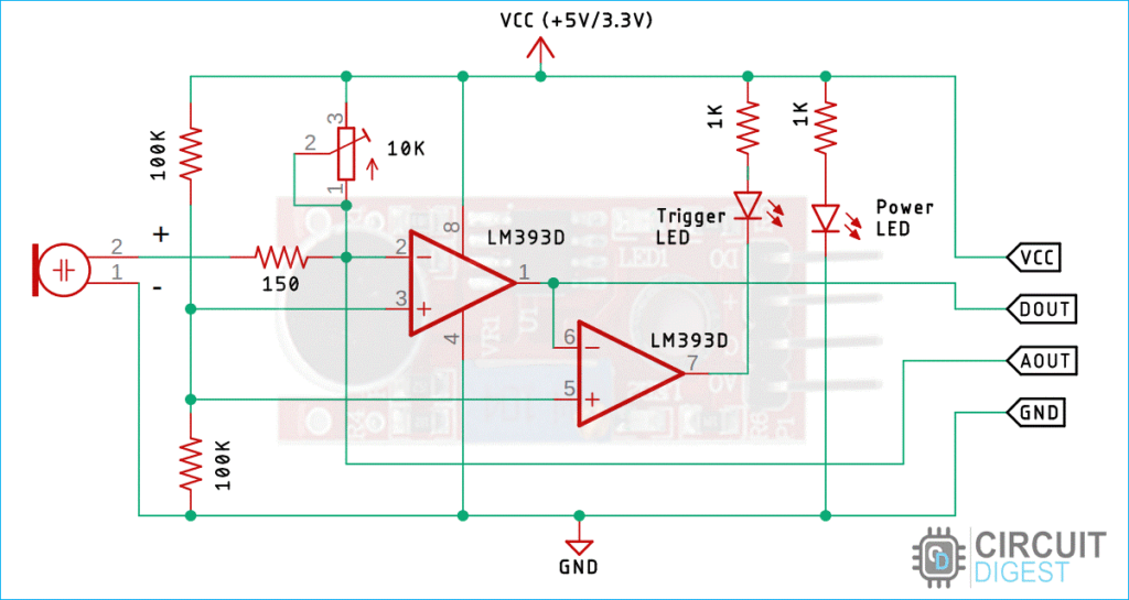
At the leftmost side, you can see the KY-038 and at the right the LM393 microphone sound sensor. Sensor module has a built-in potentiometer to adjust the sensitivity of the digital output pin.
Microphone Sound Sensor interfacing with Arduino:
This sensor module has 4 Pins of which VCC & GND are connected to 5 volts DC and ground pins of Arduino. A0 the Analog Pin of the sensor is connected A0 Analog Pin of Arduino which converts the analog voltage into Digital output. D0 is digital output which is square wave which can be connected to any digital Pin say 7 of Arduino. Then we have Red LED, Green LED and Buzzer conne cted to Pin 3, Pin 2 and Pin 4 respectively. The Green LED would light when the micro-controller is powered up. Red LED would light up and Buzzer makes sound when the sound level is above the settings.
Microphone Sound Sensor interfacing with Node MCU:
This sensor module has 4 Pins of which VCC & GND are connected to 3.3 volts DC and ground pins of Node MCU. A0 the Analog Pin of the sensor is connected ADC0 Analog Pin of Node MCU which converts the analog voltage into Digital output. D0 is digital output which is square wave which can be connected to any digital Pin say GPIO7 of Node MCU. Then we have Red LED, Green LED and Buzzer conne cted to Pin GPIO3, Pin GPIO2 and Pin GPIO4 respectively. The Green LED would light when the micro-controller is powered up. Red LED would light up and Buzzer makes sound when the sound level is above the settings.
Microphone Sound Sensor interfacing with ESP32
This sensor module has 4 Pins of which VCC & GND are connected to 3.3 volts DC and ground pins of ESP32. A0 the Analog Pin of the sensor is connected ADC0 Analog Pin of ESP32 which converts the analog voltage into Digital output. D0 is digital output which is square wave which can be connected to any digital Pin say GPIO7 of ESP32. Then we have Red LED, Green LED and Buzzer conne cted to Pin GPIO3, Pin GPIO2 and Pin GPIO4 respectively. The Green LED would light when the micro-controller is powered up. Red LED would light up and Buzzer makes sound when the sound level is above the settings.
