Magnetic Door Sensor with reed switch Interfacing
with Arduino, Node MCU, ESP32
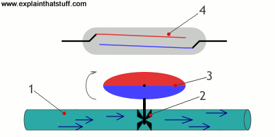
A typical reed switch contains a pair of metal reeds made of a ferromagnetic material, surfaces of the reed contacts are plated with hardening metals such as rhodium, ruthenium, palladium or iridium to give them a longer life as they switch on and off millions of times.
When the magnet is brought near the reed switch the contacts close. When the magnet is taken away the electrical circuit breaks. Electrical Contacts when open it has to break the current flowing through and this oxidizes the contacts if it is in the oxygen environment. Hence, they are put in inert gas and hermetically sealed.
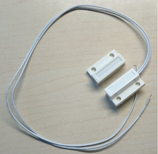
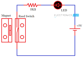
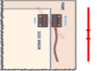
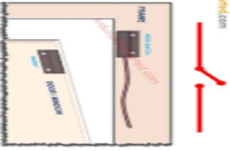
Normally the reed is ‘open’ (no connection between the two wires). The other half is a magnet. When the magnet is less than 13mm (0.5″) away, the reed switch closes and the contact is made between two wires. One part with wire is fitted on the frame of the door and is wired to Arduino. The other part viz., magnet is fixed on the door such that the distance between both elements is less than 13mm when the door is closed.
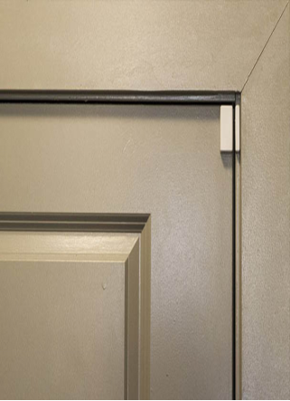
At present, door sensors are installed on the doors and windows for home security purposes. These sensors allow you to know once somebody has opened/closed a door. Many house owners utilize door sensors to guard entrances. However, these sensors work on any type of door. Actually, door sensors are so adaptable, so they are becoming very popular within activity triggers within smart home design. This article discusses an overview of a door sensor – working with applications.
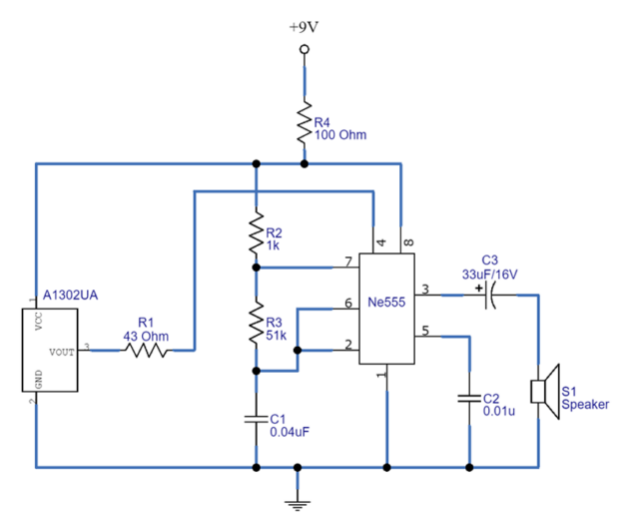
(Reset) of an IC. During the far magnet situation, the hall effect sensor works as a close switch and provides the output voltage near Vcc. In that case, Reset pin 4 becomes biased. Since this Reset pin of IC 555 is an active low pin, therefore, timer IC starts to Oscillate the pulse signal. Timer IC is connected to the loudspeaker, Output pulse duration depends on Resistors R2, R3, and Capacitor C1. By adjusting the values of these components you can get different sound tones at the loudspeaker.
Whenever the door is opened, then the magnet arranged on the door moves away from the hall sensor to generate an alert signal.
Magnetic Door Sensor with reed switch Interfacing with Arduino
Arduino 5 Volts DC is connected to one wire. Other wire is connected to 10k ohms resistor and connected to ground, midpoint of 10K is connected to Arduino Pin 8. Whenever Pin 8 gets positive pulse Arduino will make Pin 7, Pin 4 and Pin 3 high. Pin 7 is connected to relay to switch on the light. Same way Pin 4 is connected to Buzzer and Pin 3 to Red LED which turns On and buzzer as well as red LED. Whenever we want to close the door Pin 5 of the Arduino should be pulled high. Now relay will operate and close the lock. Once the door is closed the contact closes and red LED goes off, buzzer goes off. Now Green LED connected to Pin 2 will light indicating the door is locked.
Magnetic Door Sensor with reed switch Interfacing with Node MCU
Node MCU 3.3 Volts DC is connected to one wire. Other wire is connected to 10k ohms resistor and connected to ground, midpoint of 10K is connected to Node MCU Pin GPIO8. Whenever Pin GPIO8 gets positive pulse Arduino will make Pin GPIO7, Pin GPIO4 and Pin GPIO3 high. Pin GPIO7 is connected to relay to switch on the light. Same way Pin GPIO4 is connected to Buzzer and Pin GPIO3 to Red LED which turns On and buzzer as well as red LED. Whenever we want to close the door Pin GPIO5 of the Node MCU should be pulled high. Now relay will operate and close the lock. Once the door is closed the contact closes and red LED goes off, buzzer goes off. Now Green LED connected to Pin GPIO2 will light indicating the door is locked.
Magnetic Door Sensor with reed switch Interfacing with ESP32
ESP32 3.3 Volts DC is connected to one wire. Other wire is connected to 10k ohms resistor and connected to ground, midpoint of 10K is connected to ESP32 Pin GPIO8. Whenever Pin GPIO8 gets positive pulse Arduino will make Pin GPIO7, Pin GPIO4 and Pin GPIO3 high. Pin GPIO7 is connected to relay to switch on the light. Same way Pin GPIO4 is connected to Buzzer and Pin GPIO3 to Red LED which turns On and buzzer as well as red LED. Whenever we want to close the door Pin GPIO5 of the ESP32 should be pulled high. Now relay will operate and close the lock. Once the door is closed the contact closes and red LED goes off, buzzer goes off. Now Green LED connected to Pin GPIO2 will light indicating the door is locked.
