LDR Light Dependent Resistor Sensor interfacing
with Arduino, Node MCU, ESP32
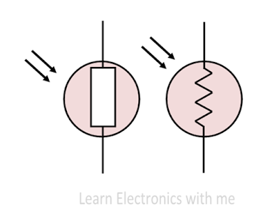
Light Dependent Resistor is called by many names such as photoresistor, photocell, photoconductor, photoconductive cells. The resistivity of LDR depends on the light incident on it and the sensitivity of LDR depends on the wavelength of the incident light. Thus it is a light sensitive device. Mostly it is used in circuits to detect the presence of the level of the light. There are many symbols. The most commonly used symbol of LDR is shown in the figure. The arrow in the symbol indicates the light falling on it.
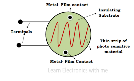
Construction of LDR: The LDR is constructed by placing a thin zigzag shaped strip of photosensitive device upon the insulating material. The light sensitive materials used in LDR are Cadmium Sulphide (Cds), Cadmium Selenide (CdSe) or lead Sulphide (Pbs). The insulating material used in LDR is ceramic. The metal films are connected with the terminal leads.
The whole structure is placed inside a plastic or resin case to have direct exposure to the sunlight. When there is no light, the resistance is very high in Mega Ohms. When the light is incident the resistance value decreases and the conductivity increases.
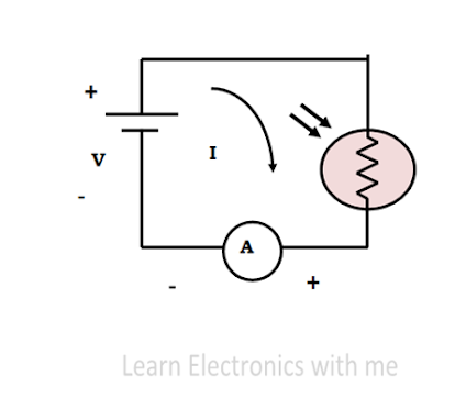
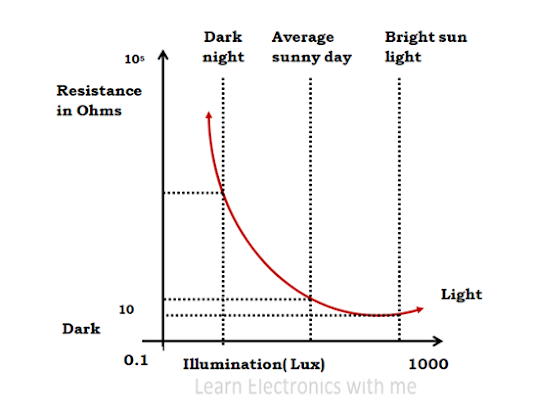
The photoconductive material does not consists of any free electrons or it consists of a few free electrons when it is not exposed to light. When the light is incident on the LDR the covalent bond breaks and many free electrons and holes are formed. The free electrons and holes gains energy and they jump from valence band to the conduction band. Thus current is generated. The resistivity of LDR decreases with increase in the incident light. More the light, more the charge carriers.
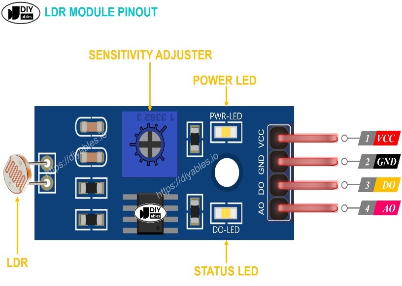
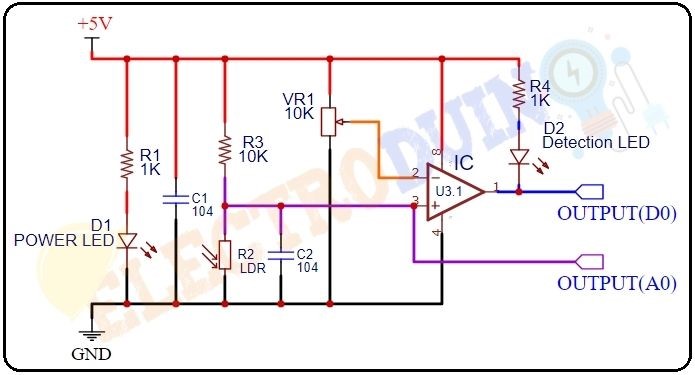
This sensor has an onboard LDR (Light Dependent Resistor), that helps it to detect light. This sensor module comes with 4 terminals. Where the “DO” pin is a digital output pin and the “AO” pin is an Analog output pin. The output of the module goes high in the absence of light and it becomes low in the presence of light. The sensitivity of the sensor can be adjusted using the onboard potentiometer. In the comparator circuit, R2 is the resistance of the LDR which drastically reduces as the intensity of the light falling on the LDR increases. The sensitivity adjuster or trim pot is adjusted such that when certain amount of light falls on LDR (as per our interest) the output triggers and we get negative square wave at the output or logic level zero.
When light intensity decreases (low/dark) on the surface of the LDR then the resistance of the LDR increases. Then the maximum amount of voltage will be allocated across the LDR (R2). So, a High amount of voltage from the LDR is given to the Inverting input (2) of the IC. Then the Comparator IC compares this voltage with the threshold voltage. In this condition, this input voltage is greater than the threshold voltage, so the sensor output goes High (1).
LDR Light Dependent Resistor Sensor interfacing with Arduino:
VCC and GND are connected to 5 volts DC and ground of Arduino. The voltage across LDR in the voltage or resistance dividing network is brought out as Analog output A0 which is connected to Analog input of Arduino A0 to which ADC (Analog to Digital Converter) is internally connected. D0 is connected to Arduino digital Pin 7 which will turn on Digital Pin 9 which is connected to relay which switches on LED Bulb. Then there are two LEDs and one buzzer connected to Pin 2, Pin 3 and Pin 4 respectively. Pin 2 is connected to Green LED which will switch on as soon as power is switch on to indicate Arduino is on. Red LED and Buzzer will be on when Pin 7 goes high.
LDR Light Dependent Resistor Sensor interfacing with Node MCU:
VCC and GND are connected to 3.3 volts DC and ground of Node MCU. The voltage across LDR in the voltage or resistance dividing network is brought out as Analog output A0 which is connected to Analog input of Node MCU ADC0 to which ADC (Analog to Digital Converter) is internally connected. D0 is connected to Node MCU digital Pin GPIO7 which will turn on Digital Pin GPIO9 which is connected to relay which switches on LED Bulb. Then there are two LEDs and one buzzer connected to Pin GPIO2, Pin GPIO3 and Pin GPIO4 respectively. Pin GPIO2 is connected to Green LED which will switch on as soon as power is switch on to indicate Node MCU is on. Red LED and Buzzer will be on when Pin GPIO7 goes high.
LDR Light Dependent Resistor Sensor interfacing with ESP32:
VCC and GND are connected to 3.3 volts DC and ground of ESP32. The voltage across LDR in the voltage or resistance dividing network is brought out as Analog output A0 which is connected to Analog input of ESP32 ADC0 to which ADC (Analog to Digital Converter) is internally connected. D0 is connected to ESP32 digital Pin GPIO7 which will turn on Digital Pin GPIO9 which is connected to relay which switches on LED Bulb. Then there are two LEDs and one buzzer connected to Pin GPIO2, Pin GPIO3 and Pin GPIO4 respectively. Pin GPIO2 is connected to Green LED which will switch on as soon as power is switch on to indicate Node MCU is on. Red LED and Buzzer will be on when Pin GPIO7 goes high.
