Industrial IoT using LDR Light Dependent Resistor Sensor coupled with Node MCU
interfaced with blinds to adjust the light inside the room using linear Actuator with Blynk App
Light Dependent Resistor is called by many names such as photoresistor, photocell, photoconductor, photoconductive cells. The resistivity of LDR depends on the light incident on it and the sensitivity of LDR depends on the wavelength of the incident light. Thus it is a light sensitive device. Mostly it is used in circuits to detect the presence of the level of the light.
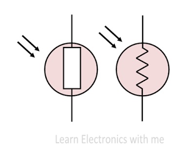
There are many symbols. The most commonly used symbol of LDR is shown in the figure. The arrow in the symbol indicates the light falling on it.

When light intensity decreases (low/dark) on the surface of the LDR then the resistance of the LDR increases. Then the maximum amount of voltage will be allocated across the LDR (R2). So, a High amount of voltage from the LDR is given to the Inverting input (2) of the IC. Then the Comparator IC compares this voltage with the threshold voltage. In this condition, this input voltage is greater than the threshold voltage, so the sensor output goes High (1).

LDR Light Dependent Resistor Sensor interfacing with Node MCU:
VCC and GND are connected to 3.3 volts DC and ground of Node MCU. The voltage across LDR in the voltage or resistance dividing network is brought out as Analog output A0 which is connected to Analog input of Node MCU ADC0 to which ADC (Analog to Digital Converter) is internally connected. D0 is connected to Node MCU digital Pin GPIO7 which will turn on Digital Pin GPIO9 which is connected to relay which switches on LED Bulb. Then there are two LEDs and one buzzer connected to Pin GPIO2, Pin GPIO3 and Pin GPIO4 respectively. Pin GPIO2 is connected to Green LED which will switch on as soon as power is switch on to indicate Node MCU is on. Red LED and Buzzer will be on when Pin GPIO7 goes high.
Using this LDR sensor, we can either switch lights to increase ambient lighting within a building as a part of Building management system when the ambient light is low or a linear actuator can be activated to move the blinds up or down to maintain illumination to required levels in the building during the bright sunny day.
Let us take the example of linear actuator: The primary role of LDR Light dependent resistor coupled with Linear actuator is to provide real-time Ambient Light control within a building during the day time as well as during night time. This data is crucial for maintaining the desired Ambient Light, ensuring best working environment reducing fatigue due to low lighting conditions or strain on the eyes due to excessive lighting. Hence on periodic basis this data pertaining to the room lighting condition is uploaded to the cloud and made available to the users on mobile using different Apps.
Light controllers using LDR Sensor coupled with Linear actuator to adjust blinds to maintain a stable and precise lighting conditions. This control process is essential for consistent productivity from the people who are working in the offices and at the same time buildings are made energy efficient.
Despite the above automation in ambient light management there can be poor lighting or too much brightness due to some malfunction of automation system in which case the push notifications will be sent to the concerned people through cloud apps.
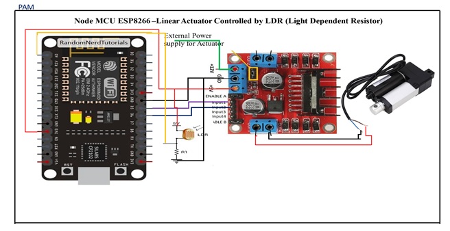
For connecting LDR Light Sensor coupled with Linear actuator to the cloud, we need to connect LDR Light Sensor & Linear actuator to ESP8266 Node MCU using motor driver amplifier and provide internet connection to Node MCU to send the data to cloud. For this Node MCU must be coded and Apps must be installed both on Node MCU and mobile phones to which data needs to be sent.
