Infrared IR proximity Obstacle sensor interfacing
with Arduino, Node MCU, ESP32
The working of the IR sensor module is very simple, it consists of two main components: the first is the IR transmitter section and the second is the IR receiver section. In the transmitter section, IR led is used which emits Infrred light which gets bounced by the object in front in the range from 0.5 cm to 1.5 cm and in the receiver section, a photodiode or a transistor.
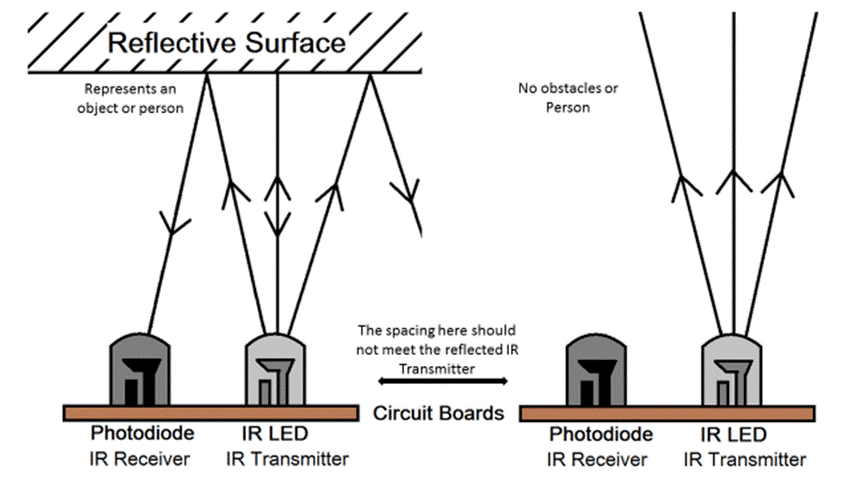
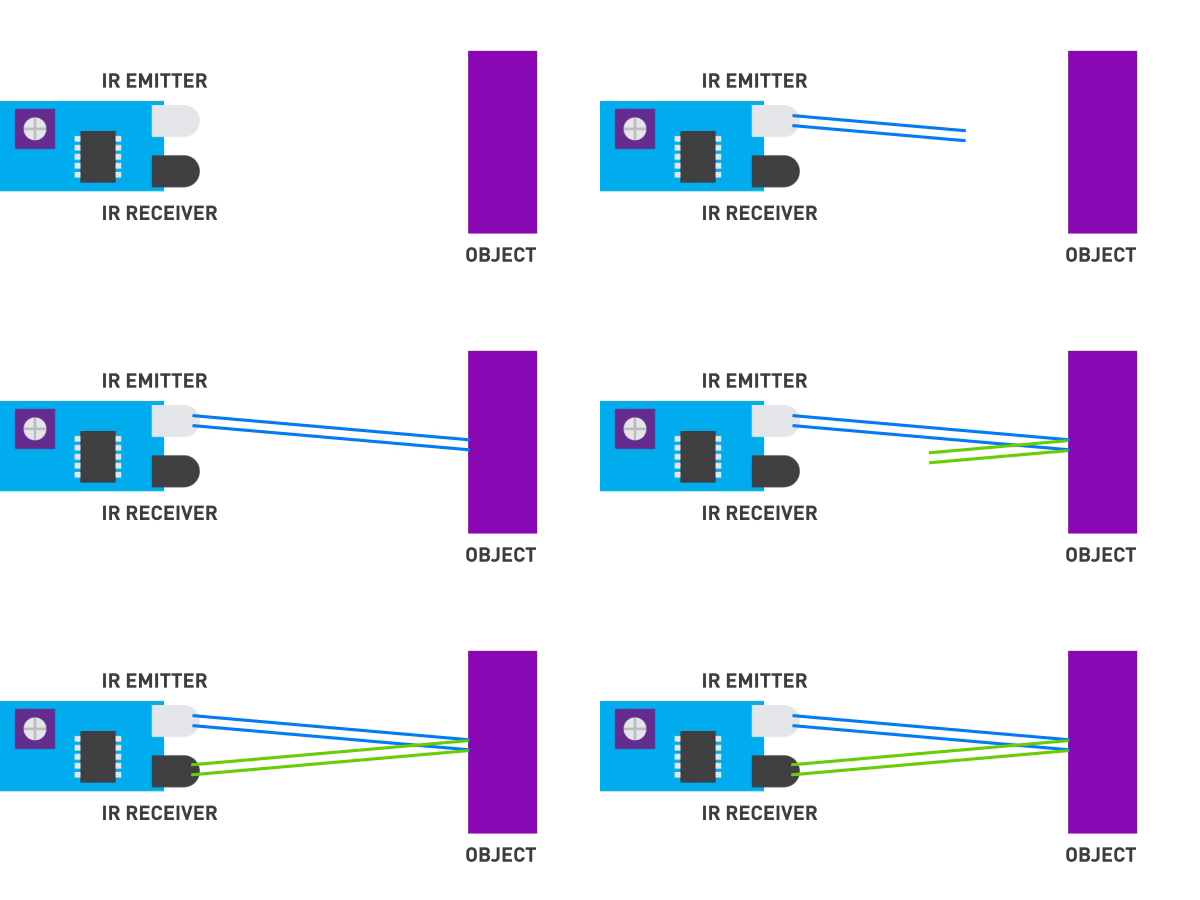
Which receives infrared signal bounced back from the obstructing object. This received signal is amplified and fed to the comparator where after filtering out the noice a fine square wave is produced which can be fed to Arduino.
When there is no obstruction in the front the IR rays transmitted by IR LED is not reflected back and consequently IR receiver does not get any return signal. Total Time taken for IR signal to travel to object and get reflected back and reach the receiver is known as time of flight. We can compute distance to the object by multimplying speed of light by half of time of flight
IR LED emits infrared light, means it emits light in the range of Infrared frequency. We cannot see Infrared light through our eyes, they are invisible to human eyes. The wavelength of Infrared (700nm – 1mm) is just beyond the normal visible light. Everything which produce heat, emits infrared like our human body. Infrared have the same properties as visible light, like it can be focused, reflected and polarised like visible light.
IR Receiver : TSOP is available in many frequency ranges like TSOP1730, TSOP1738, TSOP1740 etc. Last two digits represent the frequency (in Khz) of modulated IR rays, on which TSOP responds. Like for example TSOP1738 reacts when it receives the IR radiation modulated at 38Khz. Means it detects the IR which is switching On and Off at the rate of 38Khz.
We are using TSOP1738 as IR receiver, so we need to generate the modulated IR of 38 kHz.
You can use any TSOP, but you need to generate IR of respective frequency as TSOP. So we are using 555 timer in Astable mode to oscillate the IR at 38KHz frequency. As we know oscillation frequency of 555 timer is decided by resistor R1, R2 and capacitor C1.
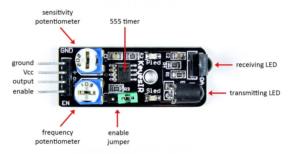
As you can see in the blow IR Transmitter Circuit We have used 1k R1, 20K R2 and 1nF capacitor to generate the frequency of approx. 38 KHz. It can be calculated using this formula: 1.44/((R1+2*R2)*C1).
Some of the sensor boards come with additional enable pin in which case it can be connected to Arduino digital Pin 8.
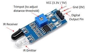
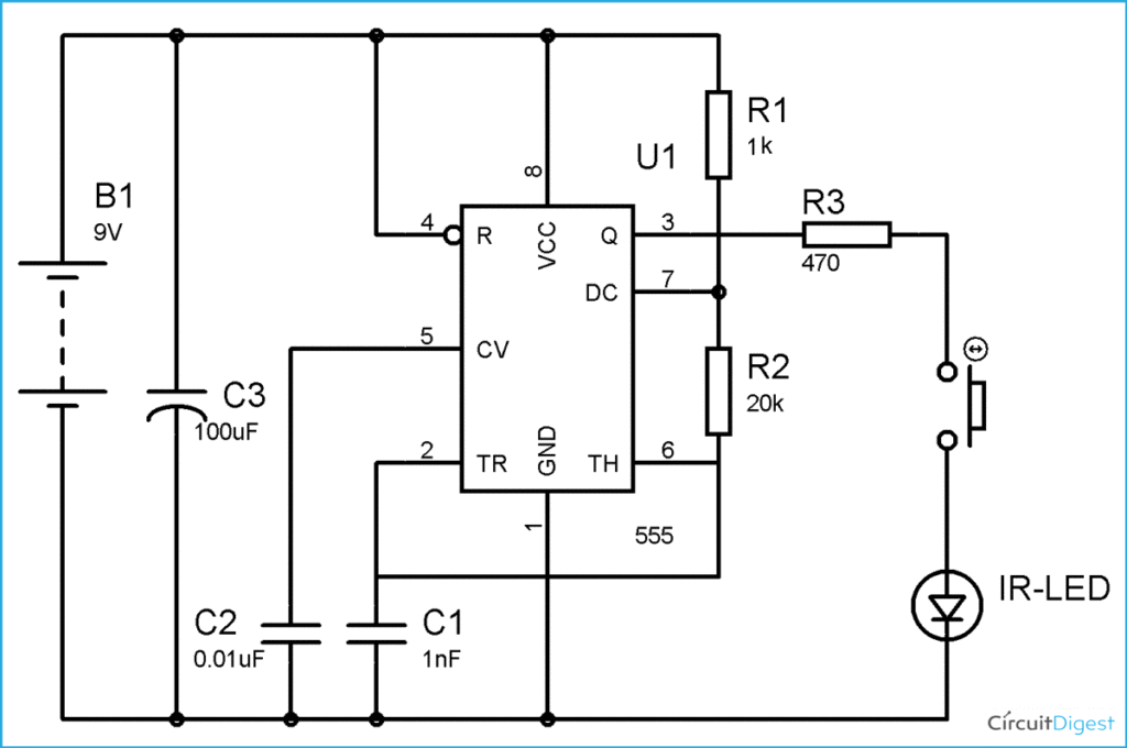
There are two potentiometers one for adjusting sensitivity and other for adjusting frequency. By adjusting sensitivity potentiometer we can adjust the distance of the reflecting object. But you need to be careful about frequency adjustment because you need to have oscilloscope to fine tune this. Most of the commonly available boards will only have single potentiometer for adjusting distance threshold. Other pins are same except that there is no enable Pin.
Infrared IR proximity Obstacle sensor with Arduino:
VCC & Gnd pins of the sensor are connected to 5 volts DC and ground pin of Arduino. Digital Output pin is connected to Pin 7 of Arduino. When Pin 7 status changes Pin 8 becomes high. Apart from this we need to connect two LEDs and one buzzer to high light certain conditions. Green LED is connected to Pin 2 of Arduino which switches on when Arduino is switched on as a power on Indicator. Then there is Red LED and buzzer which are connected to Pin 3 and Pin 4 of Arduino. When Pin 7 changes the status both pin 3 and 4 go high and Red LED and buzzer turns on.
Infrared IR proximity Obstacle sensor with Node MCU:
VCC & Gnd pins of the sensor are connected to 3.3 volts DC and ground pin of Node MCU. Digital Output pin is connected to Pin GPIO7 of Node MCU. When Pin GPIO7 status changes Pin GPIO8 becomes high. Apart from this we need to connect two LEDs and one buzzer to high light certain conditions. Green LED is connected to Pin GPIO2 of Arduino which switches on when Node MCU is switched on as a power on Indicator. Then there is Red LED and buzzer which are connected to Pin GPIO3 and Pin GPIO4 of Node MCU. When Pin GPIO7 changes the status both pin GPIO3 and GPIO4 go high and Red LED and buzzer turns on.
Infrared IR proximity Obstacle sensor with ESP32:
VCC & Gnd pins of the sensor are connected to 3.3 volts DC and ground pin of ESP32. Digital Output pin is connected to Pin GPIO7 of ESP32. When Pin GPIO7 status changes Pin GPIO8 becomes high. Apart from this we need to connect two LEDs and one buzzer to high light certain conditions. Green LED is connected to Pin GPIO2 of ESP32 which switches on when ESP32 is switched on as a power on Indicator. Then there is Red LED and buzzer which are connected to Pin GPIO3 and Pin GPIO4 of ESP32. When Pin GPIO7 changes the status both pin GPIO3 and GPIO4 go high and Red LED and buzzer turns on.
