Industrial IoT using SN04-P PNP 5mm Inductive Proximity Sensor Interface with
Node MCU with LCDisplay, Blynk App and Thingspeak App and counting
An inductive sensor is a non-contact type of sensor, helpful in the detection of metallic objects. It can sense ferrous as well as non-ferrous materials. The sensing range is up to 100 mm. There are mechanical switches such as bump switches which are contact detection switches. This means if the object is in touch with the switch, then only it will operate. Over a period of time there will be wear and tear and we need to replace the switch.
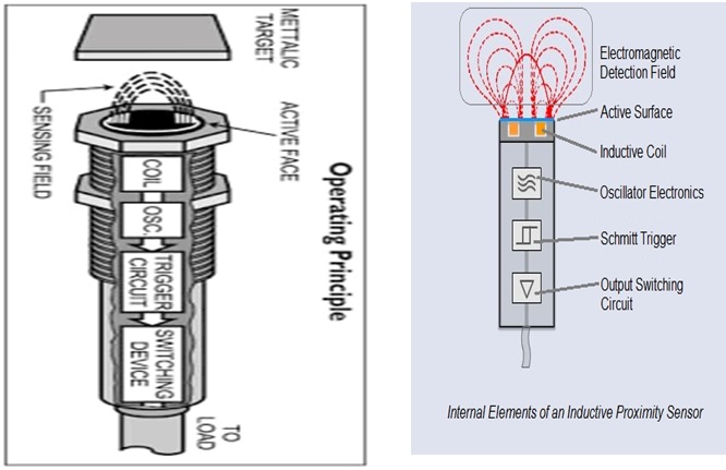
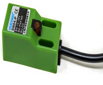
This is not the case in the inductive sensor. Inductive proximity sensors have solid-state assembly – no moving parts. They work on proximity basis and as such there will be no physical contact and hence no wear and tear consequently offering a long life.
Working principle of most of the inductive sensors is almost similar. There will be an LC oscillator inside a tube like structure which produces electro-magnetic field. When any metal piece cuts into the magnetic field oscillations dampen due to eddy currents produced in the metal piece. This change in amplitude is gauged to trigger NPN or PNP transistor.
The trigger circuit is normally a Schmitt trigger. It monitors the amplitude of an oscillator. If the oscillator’s amplitude reaches a predetermined level, the trigger circuit gives the signal to the output circuit to switch-ON the output. This gives a perfect square wave which can be read by Arduino controller.
Advantages of Inductive Proximity Sensors
- Contactless sensing.
- High switching rate.
- Long-life as no moving parts are there.
- Easy installation.
- Disadvantages of Inductive Proximity Sensors
- Can sense only metal.
- Range detection limitation. The maximum detection range is 100mm.
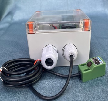
Since these proximity sensors have inductance in them, we cannot power them using Arduino power supply as inductance may release high energy at times which can destroy Arduino. Further the voltage requirements of inductive proximity sensor is much higher typically about 12 volts though the specification says 6 to 36 volts DC external power supply. Ground Pin of this external power supply and Arduino board must be tied together to avoid circulating current.
Switch types can be normally open (NO) or normally closed (NC). When a metal target enters the magnetic field created by coil, eddy current circulates within the target. This causes load on the sensor which decreases the oscillator’s amplitude. As the target reaches close to the sensor further the oscillator’s amplitude decreases. This operates and switch from NO to NC and also switches an LED indicator.
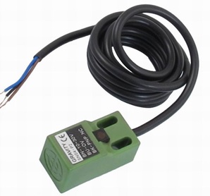
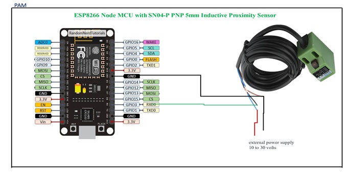
SN04-P PNP 5mm Inductive Proximity Sensor Interface with Node MCU
The sensor has 3 terminals. Blue wire is connected to Node MCU ground as well as external power supply ground. Brown wire is connected to external power supply 10 volts to 30 volts plus side. As stated earlier do not try to power up this sensor from Node MCU directly if done Node MCU surely get damaged. Black wire is signal out which can be connected to Pin GPIO7 of Node MCU. When Pin GPIO7 gets activated from the sensor, we can operate a relay by pulling pin GPIO12 of Node MCU high. The relay contacts have external power supply of 12 volts DC which switches 12 volts DC bulb connected in series with NO contact.
There are two LEDs and one buzzer connected to board. The green LED would turn on as soon as Node MCU is powered up. This LED is connected to pin 2 of Node MCU. Then we have Red LED and Buzzer connected to Node MCU Pin 3 and Pin 4 which switches on whenever the proximity sensor detects any metal object in its range.
