Humidity and Temperature sensor DHT11 interfacing
with Arduino, Node MCU, ESP32 and LCD Display
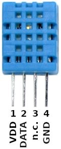
DHT 11 is an economical and simple humidity and temperature sensor. It can measure humidity from 20-90% RH with an Accuracy: ±5% RH. Similarly it can measure temperature from 0-50 °C with an Accuracy: ±2% °C.
Working principle of DHT11: There are two components of DHT11 viz.,Humidity sensor and Temperature sensor which work independent of each other.
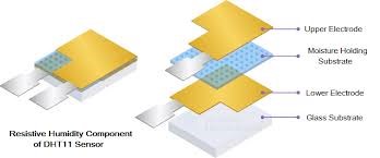
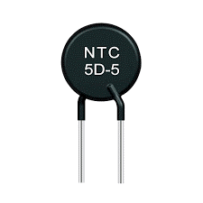
Humidity sensor has a moisture holding substrate in between two electrodes upper and the lower. Together they form a capacitor whose value would change based on the amount of moisture which depends on the level of humidity in the air. The temperature is measured using thermistor which is most economical way of measuring temperature. Even though thermistor has a limited range that would suffice our application as we would be measuring only from 0 to 50 degree centigrade.
Even though thermistor has a limited range that would suffice our application as we would be measuring only from 0 to 50 degree centigrade.
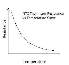
Even though temperature verses resistance characteristic is non-linear for the range of temperature which of interest to us it will not make much of a difference. Thermistor has the ability to change its resistance drastically for a small change in temperature. DHT11 has a built in SoC (System on Chip) or a small micro-computer built in with its own ADC (Analog to Digital converter) of 8 bit which would suffice our desired accuracy for both temperature and humidity.
Thermistors are generally produced using powdered metal oxides or semiconductor made of ceramic materials and in both cases their resistance changes dramatically with temperature (by 100 ohms or more per degree).

The term “NTC” stands for “Negative Temperature Coefficient,” which means that resistance decreases as temperature rises. Same way we also have PTC thermistors where the thermistors resistance increases as the temperature increases. However, in both the cases the characteristics are non linear as you can see in the picture above. We can use The Steinhart– Hart equation is a model of the resistance of a semiconductor at different temperatures where A, B and C are constants.
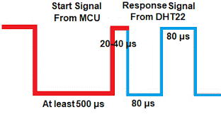
The communication between Arduin, Node MCU or ESP32 and DHT is in the form of train of pulses using single wire. When MCU sends a start signal, DHT11 changes from the low-power-consumption mode to the running mode, waiting for MCU to complete the start signal. Once it is completed, DHT11 sends a response signal of 40-bit data that include the relative humidity and temperature information to the MCU.
Complete data transmission is 40bit, and the sensor sends higher data bit first. Data format is as follows: 8bit integral RH data + 8bit decimal RH data + 8bit integral T data + 8bit decimal T data + 8bit checksum. If the data transmission is right, the check-sum should be the last 8bit of “8bit integral RH data + 8bit decimal RH data + 8bit integral T data + 8bit decimal T data”.
Humidity and Temperature sensor DHT11 interfacing with Arduino
There are 3 pins on the DHT11 sensor, Pin 1 is connected to ground of Arduino, Pin 2 is connected to VCC of Arduino and Pin 3 is connected to digital Pin 7 of Arduino. We also need to connect Green LED to Pin 2, Red LED to Pin 3 and Buzzer to Pin 4 of Arduino. Green LED will switch on whenever Arduino is switched on to indicate Power on. Red LED and buzzer will switch on whenever temerature exceeds the set limit. The current limiting resistors are connected in ground circuit and all 3 are tied together and connected to Arduino ground.
Humidity and Temperature sensor DHT11 interfacing with Node MCU
There are 3 pins on the DHT11 sensor, Pin 1 is connected to ground of Node MCU, Pin 2 is connected to 3.3 volts of Node MCU and Pin 3 is connected to digital Pin GPIO7 of Node MCU. We also need to connect Green LED to Pin GPIO2, Red LED to Pin GPIO3 and Buzzer to Pin GPIO4 of Node MCU. Green LED will switch on whenever Arduino is switched on to indicate Power on. Red LED and buzzer will switch on whenever temerature exceeds the set limit. The current limiting resistors are connected in ground circuit and all 3 are tied together and connected to Node MCU ground.
Humidity and Temperature sensor DHT11 interfacing with ESP32
There are 3 pins on the DHT11 sensor, Pin 1 is connected to ground of ESP32, Pin 2 is connected to 3.3 volts of ESP32 and Pin 3 is connected to digital Pin GPIO7 of ESP32. We also need to connect Green LED to Pin GPIO2, Red LED to Pin GPIO3 and Buzzer to Pin GPIO4 of ESP32. Green LED will switch on whenever Arduino is switched on to indicate Power on. Red LED and buzzer will switch on whenever temerature exceeds the set limit. The current limiting resistors are connected in ground circuit and all 3 are tied together and connected to ESP32 ground.
