Force Sensitive Resistor (FSR)
Interfacing with Arduino, Node MCU, ESP32
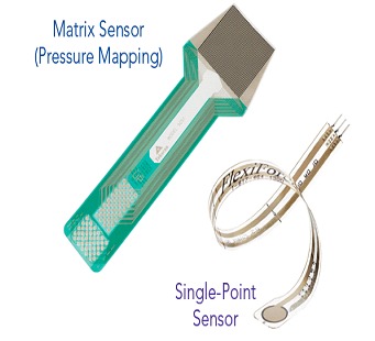
Matrix or Single-Point Force Sensing Resistors: Examples of different force sensitive resistor technologies. Force sensing resistors can be designed as single-point force sensors, or in a matrix array form, allowing the user to capture pressure distribution over a given area. Force sensing resistor matrices are commonly referred as pressure mapping technology.
Force sensor or Force Sensitive Resistor is a type of transducer which converts an input mechanical force such as load, weight, tension, compression or pressure into another physical variable such as electrical output signal that can be measured. As the force applied to the force sensor increases, the electrical signal changes proportionally.
Force Transducers became an essential element in many industries where reliable and high precision measurement is paramount. FSR is basically a resistor that changes its resistance value (in ohms Ω) depending on how much it is pressed. These are low cost, easy to use but are not very accurate. When you use FSRs you should only expect to get a reasonable response. While FSRs can detect weight, they are not a good choice for detecting exact weight.
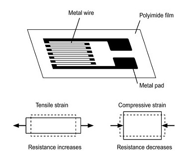
FSR has electrical conductors tightly attached to a film in a zigzag shape. When this film is pressed change in shape causes the resistance in the electrical conductors to also change.
Resistance range: Infinite/open circuit (no pressure), 100KΩ (light pressure) to 200Ω (max. pressure)
Force range: 0 to 20 lb. (0 to 100 Newtons) applied evenly over the 0.125 square inch surface area
How are Force Sensing Resistors Made?
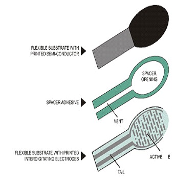
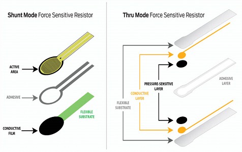
Force sensing resistors consist of a semi-conductive material – or, semi-conductive ink – contained between two thin substrates. As shown in Figure 2, there are two different types of force sensing resistor technologies – Shunt Mode, and Thru Mode.
Figure 2: This graphic illustrates the differences between shunt and thru mode force sensing resistor technologies.
Shunt mode force sensing resistors are polymer thick-film devices consisting of two membranes separated by a thin air gap. One membrane has two sets of interdigitated traces that are electronically isolated from one another, while the other membrane is coated with a special textured, resistive ink.
Thru mode force sensing resistors are flexible printed circuits that utilize a polyester film as its two outer substrates. Silver circles with traces are positioned above and below a pressure-sensitive layer, followed by a conductive polymer. An adhesive layer is used to laminate the two layers of the substrate together.
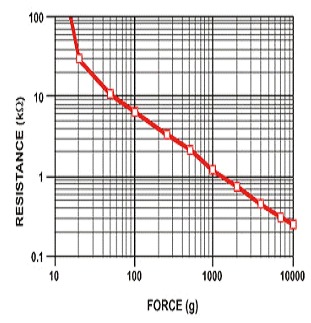
As said, the FSR’s resistance changes as more pressure is applied. When there is no pressure, the sensor looks like an infinite resistor (open circuit) and as the pressure increases, the resistance goes down. This graph indicates approximately the resistance of the sensor at different force measurements. It is important to notice that the graph is not really linear and at especially low force measurements it quickly goes from infinite to 100KΩ. Force Sensing module provides 4 Pins viz., Ground, VCC, NC (Not connected) and Output. Output is proportional to force applied, if we create resistance or voltage dividing network and feed this Analog output Arduino Uno Analog port then we can read the force on LCD monitor.
Force Sensitive Resistor (FSR) interfacing with Arduino:
VCC and GND of FSR sensor board is connected to 5 volts and ground of Arduino. The Vout is connected to A0, ADC (Analog to Digital converter) which converts the Analog input into equivalent digital output and displays it on LCD monitor. Apart from this we have two LEDs and one buzzer to be connected. The green LED is connected to Pin 2 of the Arduino which lights up whenever Arduino is switched on. Red LED and Buzzer is connected to Pin 3 and Pin 4 of the Arduino. This is set to any limit we wish and Red LED would light up and buzzer makes sound when this limit is reached.
Force Sensitive Resistor (FSR) interfacing with Node MCU:
VCC and GND of FSR sensor board is connected to 3.3 volts and ground of Node MCU. The Vout is connected to ADC0, ADC (Analog to Digital converter) which converts the Analog input into equivalent digital output and displays it on LCD monitor. Apart from this we have two LEDs and one buzzer to be connected. The green LED is connected to Pin GPIO2 of the Node MCU which lights up whenever Node MCU is switched on. Red LED and Buzzer is connected to Pin GPIO3 and Pin GPIO4 of the Node MCU. This is set to any limit we wish and Red LED would light up and buzzer makes sound when this limit is reached.
Force Sensitive Resistor (FSR) interfacing with ESP32:
VCC and GND of FSR sensor board is connected to 3.3 volts and ground of ESP32. The Vout is connected to ADC0, ADC (Analog to Digital converter) which converts the Analog input into equivalent digital output and displays it on LCD monitor. Apart from this we have two LEDs and one buzzer to be connected. The green LED is connected to Pin GPIO2 of the ESP32 which lights up whenever ESP32 is switched on. Red LED and Buzzer is connected to Pin GPIO3 and Pin GPIO4 of the ESP32. This is set to any limit we wish and Red LED would light up and buzzer makes sound when this limit is reached.
