Distance Measurement using Ultrasonic Sensor HC-SR04
with Arduino, Node MCU, ESP32 Displayed on OLED


Ultrasonic sensors are electronic devices that calculate the target’s distance by emission of ultrasonic sound waves and convert those waves into electrical signals. The speed of emitted ultrasonic waves traveling speed is faster than the audible sound.
D = 1/2 T * C
Where ‘T’ corresponds to time measured in seconds
‘C’ corresponds to sound speed = 343 measured in mts/sec
Ultrasonic sensor working principle is either similar to sonar or radar which evaluates the target/object attributes by understanding the received echoes from sound/radio waves correspondingly. These sensors produce high-frequency sound waves and analyze the echo which is received from the sensor. The sensors measure the time interval between transmitted and received echoes so that the distance to the target is known.
There are many types of Arduino distance sensors, but in this project we have used the HC-SR04 to measure distance in range of 2cm-400cm with an accuracy of 3mm. The sensor module consists of an ultrasonic transmitter, receiver and control circuit. The working principle of ultrasonic sensor is as follows:
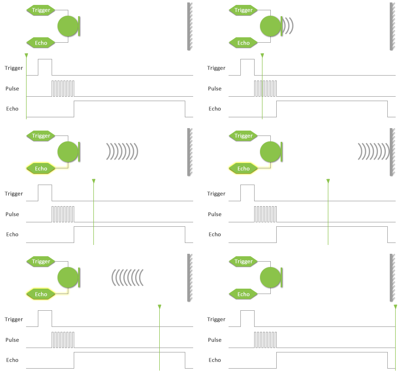
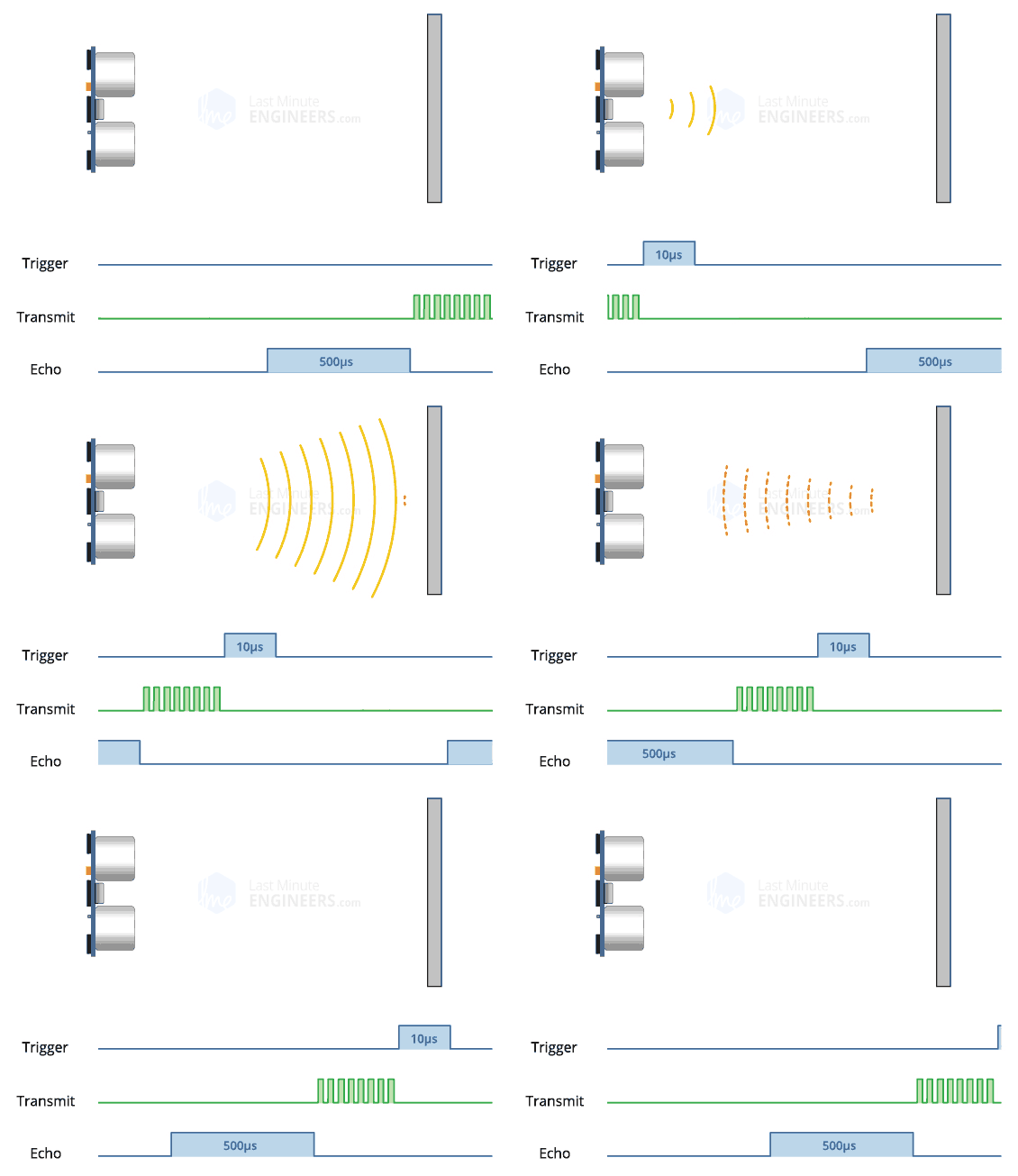
High level signal is sent for 10us using Trigger.
The module sends eight 40 KHz signals automatically, and then detects whether pulse is received or not.

If the signal is received, then it is through high level. The time of high duration is the time gap between sending and receiving the signal.
Distance= (Time x Speed of Sound in Air (340 m/s))/2
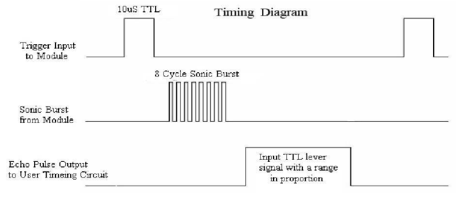
Timing Diagram
The module works on the natural phenomenon of ECHO of sound. A pulse is sent for about 10us to trigger the module. After which the module automatically sends 8 cycles of 40 KHz ultrasound signal and checks its echo. The signal after striking with an obstacle returns back and is captured by the receiver. Thus the distance of the obstacle from the sensor is simply calculated by the formula given as
Distance= (time x speed)/2.
Here we have divided the product of speed and time by 2 because the time is the total time it took to reach the obstacle and return back. Thus the time to reach obstacle is just half the total time taken.
These devices are also termed ultrasonic transceivers because both the transmitter and receiver sections are combined in a single unit which considerably minimizes the PCB footprint.
Here, the sensor operates as a burst signal and it is transmitted for some period. Later the transmission, there exists a silent period and this period is termed response time. The response time indicates that it is waiting for the reflected waves.

The shape of the acoustic waves that leave the transmitter section resembles the same shape of the light emitted from a laser so beam angle and spread have to be measured. When the sound waves move away from the transmitter, the detection area increases vertically and sideways too. Because of the varying detection area, the coverage specification is considered either as beam angle/beamwidth other than the standard area of detection.
It is more recommended to observe the beam angle pattern for the sensor whether it is the complete angle of the beam or the angle of variation corresponding to the straight line that forms a transducer. Mostly, a thin beam angle results in a higher detection range, and a broader beam angle corresponds to a lesser detection range.
The transmitted/acoustic signals might find a hindrance or not. When there is any hindrance, the acoustic wave bounces back from the hindrance. This bounced signal is termed ECHO. This echo travels to the receiver.
Then the received signal is either filtered or amplified and then transformed into a digital signal. With the time between transmission and reception of acoustic waves, the distance between the ultrasonic system and hindrance can be known.
Distance Measurement using Ultrasonic Sensor HC-SR04 with Arduino:
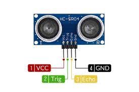
Ultrasonic Sensor has 4 Pins of which VCC and GND are connected to Arduino 5 volts DC and ground respectively. Trigger is connected to Pin 7 and Echo is connected to Pin 8. SCL (Clock) and SDA (Data) Pins of the sensor are connected to Analog Pin A5 and Pin A4 of Arduino respectively. The distance of the object is computed by Arduino and displayed.
Distance Measurement using Ultrasonic Sensor HC-SR04 with Node MCU:
Ultrasonic Sensor has 4 Pins of which VCC and GND are connected to Node MCU 3.3 volts DC and ground respectively. Trigger is connected to Pin GPIO7 and Echo is connected to Pin GPIO8 of Node MCU. SCL (Clock) and SDA (Data) Pins of the sensor are connected to Pin GPIO5 and Pin GPIO4 of Node MCU respectively. The distance of the object is computed by Node MCU and displayed.
Distance Measurement using Ultrasonic Sensor HC-SR04 with ESP32:
Ultrasonic Sensor has 4 Pins of which VCC and GND are connected to ESP32 3.3 volts DC and ground respectively. Trigger is connected to Pin GPIO7 and Echo is connected to Pin GPIO8 of ESP32. SCL (Clock) and SDA (Data) Pins of the sensor are connected to Pin GPIO22 and Pin GPIO21 of ESP32 respectively. The distance of the object is computed by ESP32 and displayed.
