Digital Clock using DS3231 Real Time Clock interfaced
with Arduino, Node MCU, ESP32 and Seven Segment Display
Real-time clock is a clock function used by systems that measure time even when the main device (such as MCU) is powered off. For example, even when the main battery or power supply is removed from a camera or gaming device, system can measure time by powering the real-time clock from a sub-battery or super capacitor built into that system.
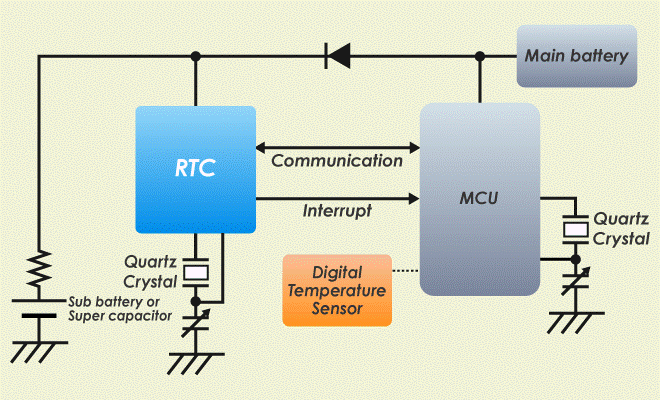
real-time clock achieves longer battery life by ultra-low current consumption. RTC has various time management solutions including high accuracy clock correction function, constant 32kHz output, expansion alarm, 24 bit up counter and ultra-small package.
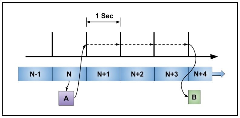
The real-time clock’s basic function is to produce intervals of one second and maintain a continuous count. You can see a representation of this in the diagram below. Also shown is a program function, A, reading a seconds counter and scheduling an event, B, to occur three seconds in the future. This action is called an alarm. Notice the seconds counter runs continuously and does not stop and start. Two primary requirements of an RTC are accuracy and continuous operation.

An RTC often has its own internal oscillator with an external crystal and an option to use an external frequency reference. All clock sources run at 32,768 Hz. An external clock source allows the use of a very accurate and stable device such as a TCXO (temperature-compensated crystal oscillator).
A clock source is selected with a multiplexer and input to a prescaler which divides the clock by a factor of 32,768 (215) to produce a one-second clock. A basic RTC has a seconds counter which is usually 32 bits or more. Some RTCs have specialized counters to keep track of the time of day and the calendar date.
A basic RTC without time and date counters uses software for this purpose. A common option is a 1 Hz square wave from an output pin. An RTC will have several possible events to generate a processor interrupt.
An RTC often has a dedicated power pin to allow operation when the rest of the microcontroller is powered down. This power pin is typically connected to a battery or separate power supply.
The next diagram shows common hardware features of an RTC.
Low current consumption of 0.25μA: real-time clock achieves longer battery life by ultra-low current consumption of 0.25µA. When using a rechargeable lithium-ion battery (3.4mAh) for backup, long-time driving of up to 13,000 hours is possible. Users are able to use smaller batteries, promoting high-density mounting.
DS3231 Real Time Clock
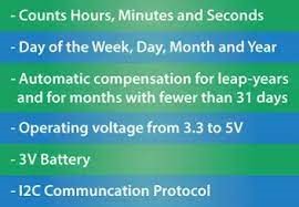
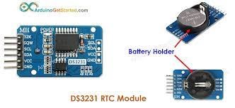
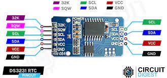
The DS3231 is a low-cost, highly accurate Real Time Clock which can maintain hours, minutes and seconds, as well as, day, month and year information. Also, it has automatic compensation for leap-years and for months with fewer than 31 days. The module can work on either 3.3 or 5 V which makes it suitable for many development platforms or microcontrollers. The battery input is 3V and a typical CR2032 3V battery can power the module and maintain the information for more than a year.
DS3231 Real Time Clock interfaced with Arduino:
DS3231 Real Time Clock has 6 Pins of which VCC and GND are connected to 5 volts DC and ground Pin of Arduino respectively. 32K pin out is Oscillator output, SQW is square output could be used for counters using Arduino. The module uses the I2C Communication Protocol which makes the connection to the Arduino Board quite easy. The SCL (Clock) be connected to Analog Pin A5, SDA (Data) is connected to Analog Pin A4. The display of time can be in any one of the forms.
DS3231 Real Time Clock interfaced with Node MCU:
DS3231 Real Time Clock has 6 Pins of which VCC and GND are connected to 3.3 volts DC and ground Pin of Node MCU respectively. 32K pin out is Oscillator output, SQW is square output could be used for counters using Node MCU. The module uses the I2C Communication Protocol which makes the connection to the Node MCU Board quite easy. The SCL (Clock) be connected to Node MCU Pin GPIO5 and SDA (Data) is connected to GPIO4 Pin. The display of time can be in any one of the forms.
DS3231 Real Time Clock interfaced with ESP32:
DS3231 Real Time Clock has 6 Pins of which VCC and GND are connected to 3.3 volts DC and ground Pin of ESP32 respectively. 32K pin out is Oscillator output, SQW is square output could be used for counters using ESP32. The module uses the I2C Communication Protocol which makes the connection to the Node MCU Board quite easy. The SCL (Clock) be connected to ESP32 Pin GPIO22 and SDA (Data) is connected to GPIO21 Pin. The display of time can be in any one of the forms.
