Capacitive Soil Moisture Sensor Interfaced
with Arduino, Node MCU, ESP32 with LCD Display

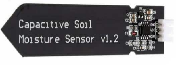
The capacitive soil moisture sensor is different from most of the resistive sensors on the market, using the principle of capacitive induction to detect soil moisture. It avoids the problem that resistive sensors are highly susceptible to corrosion and greatly extends its working life.
It is made of corrosion-resistant materials and has an excellent service life. Insert it into the soil around plants and monitor real-time soil moisture data. The module includes an on-board voltage regulator that allows it to operate over a voltage range of 3.3 ~ 5.5 V. It is ideal for low-voltage microcontrollers with 3.3 V and 5 V supplies.
The hardware schematic of the capacitive soil moisture sensor is shown below. There is a fixed frequency oscillator, which is built with a 555 timer IC. The generated square wave is then fed to the sensor like a capacitor. However, for the square wave signal, the capacitor has a certain reactance or, for the sake of argument, a resistor with a pure ohmic resistor (10k resistor on pin 3) to form a voltage divider.

The higher the soil moisture, the higher the capacitance of the sensor. As a result, the square wave has less reactance, which reduces the voltage on the signal line, and the smaller the value of the Analog input through the microcontroller.
Most capacitors contain at least two electrical conductors often in the form of metallic plates or surfaces separated by a dielectric medium. A capacitive moisture sensor works by measuring the changes in capacitance caused by the changes in the dielectric. The Soil Moisture Sensor uses capacitance to measure dielectric permittivity of the surrounding medium. In soil, dielectric permittivity is a function of the water content. The sensor creates a voltage proportional to the dielectric permittivity, and therefore the water content of the soil. Soil moisture basically refers to the amount of water content present in the soil. This can be measured using a soil moisture sensor either using resistive or capacitive type of sensor. Here we will use Capacitive Soil Moisture Sensor. This sensor measures the volumetric content of water inside the soil and gives us the moisture level as output.
It is made of corrosion-resistant material which gives it excellent service life. Insert it into the soil around your plants and monitor the real-time soil moisture data. The greater is the soil moisture, higher the capacitance of the sensor. This results in a smaller reactance to the square wave, thus lowering the voltage on the signal line. The voltage on the Analog signal pin is measured by an Analog pin on the Arduino which represents the humidity in the soil.
Capacitive Soil Moisture Sensor Interfaced with Arduino:
There are only 3 pins on the soil sensor. VCC and GND Pins of sensor are connected to Arduino 5 volts supply and Ground Pin respectively. Analog Out or Aout is connected to A0 of the Arduino board which converts Analog input into Digital output proportional to Analog value. This value is directly displayed on LCD panel which is interfaced with Arduino using I2C interface. Then there are two LEDs and one buzzer which are connected to Arduino so that certain information is displayed. The green LED is connected to Pin 2 of the Arduino which lights up whenever Arduino is powered up indicating Arduino is on. Then we have Red LED and Buzzer which can be set to trigger when the soil moisture goes almost zero the output voltage of 3 and 4 will go high which lights Red LED and Buzzer starts making sound.
Capacitive Soil Moisture Sensor Interfaced with Node MCU
There are only 3 pins on the soil sensor. VCC and GND Pins of sensor are connected to Node MCU 3.3 volts supply and Ground Pin respectively. Analog Out or Aout is connected to ADC0 of the Node MCU board which converts Analog input into Digital output proportional to Analog value. This value is directly displayed on LCD panel which is interfaced with Node MCU using I2C interface. Then there are two LEDs and one buzzer which are connected to Node MCU so that certain information is displayed. The green LED is connected to Pin GPIO2 of the Node MCU which lights up whenever Node MCU is powered up indicating Node MCU is on. Then we have Red LED and Buzzer which can be set to trigger when the soil moisture goes almost zero the output voltage of GPIO3 and GPIO4 will go high which lights Red LED and Buzzer starts making sound.
Capacitive Soil Moisture Sensor Interfaced with ESP32
There are only 3 pins on the soil sensor. VCC and GND Pins of sensor are connected to ESP32 3.3 volts supply and Ground Pin respectively. Analog Out or Aout is connected to ADC0 of the ESP32 board which converts Analog input into Digital output proportional to Analog value. This value is directly displayed on LCD panel which is interfaced with ESP32 using I2C interface. Then there are two LEDs and one buzzer which are connected to ESP32 so that certain information is displayed. The green LED is connected to Pin GPIO2 of the ESP32 which lights up whenever ESP32 is powered up indicating ESP32 is on. Then we have Red LED and Buzzer which can be set to trigger when the soil moisture goes almost zero the output voltage of GPIO3 and GPIO4 will go high which lights Red LED and Buzzer starts making sound.
