Bump Sensor Limit switches crash, collision sensor interfaced
with Arduino, Node MCU, ESP32

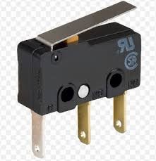
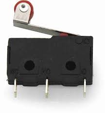
Mechanical Limit switches consist of an actuator with operating head, the switch body mechanism, and a series of electrical terminals that are used to connect the switch to the electrical circuit that it is controlling. The operating head is the part of the limit switch that comes in contact with the target. The actuator is connected to the operating head, whose linear, perpendicular, or rotary motion is then translated by the actuator to close or open the switch. The switch body contains the switch contact mechanism whose state is controlled by the actuator. The electrical terminals are connected to the switch contacts and enable wires to be joined to the switch through terminal screws or by soldering.

In most cases, a limit switch begins operating when a moving machine or a moving component of a machine makes contact with an actuator or operating lever that activates the switch. The limit switch then regulates the electrical circuit that controls the machine and its moving parts. These switches can be used as pilot devices for magnetic starter control circuits, allowing them to start, stop, slow down, or accelerate the functions of an electric motor. Limit switches can be installed into machinery as control instruments for standard operations or as emergency devices to prevent machinery malfunction. Most switches are either maintained contact or momentary contact models.
Most limit switches are mechanical in their operation and contain heavy-duty contacts capable of switching higher currents than those of alternative proximity sensors.
Micro Limit Switches: The micro limit switch, or micro switch, is another type of limit switch commonly found on control circuits. These switches are much smaller than their standard counterparts, allowing them to be installed in narrow or cramped spaces that would normally be inaccessible to other switches. Micro switches usually have an actuating plunger that only has to travel a small distance in order to trigger the contact sequence.
Subminiature micro switches are intended for use in applications requiring compact designs and limited space availability. They have contact arrangements with spring-loading mechanisms similar to those of micro switches but tend to be from one-half to one-quarter the size of regular micro switches.

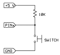
The Limit switch provides 1 NO + 1 NC contact with 1 common point. So connecting limit switch to Arduino we shall connect common point to Arduino 5 volts DC. Then NO contact shall be connected to Pin 8 of Arduino. When limit switch operates due to mechanical movement the contact closes and 5 volts is extended to Pin 8. A pull down resistor of 10K must be connected between Pin 8 and ground to make sure positive 5 volts is presented.
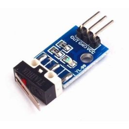
Crash sensors, collision sensors are break boards incorporating bump sensor, limit switches with additional electronic circuitry so that they can be interfaced with micro-controllers directly.
Collision sensors, also known as collision detection sensors, play a vital role in various industries, significantly improving safety and operational efficiency. Moreover, these sensors have a critical function: to detect nearby obstacles, objects, or entities and activate a response to prevent collisions or accidents. Let’s delve into the importance of collision sensors, their applications, and key features.

Collision sensors excel at detecting objects and obstacles in close proximity, delivering immediate feedback to avert collisions. Furthermore, they possess high sensitivity, enabling
effective detection of even small or low-contrast objects. Additionally, these sensors are recognized for their quick response times, rendering them suitable for dynamic, fast-paced environments. Moreover, many collision sensors easily adapt and integrate into a variety of systems and platforms. Consequently, they provide a cost-effective solution for enhancing safety and efficiency across industries, representing a prudent investment for businesses seeking accident reduction and heightened productivity.
Bump Sensor Limit switches crash, collision sensor interfaced with Arduino
Bump sensor has three pins of which one is connected to 5 volts DC, other to GND and third pin with 10 K connected through switch to ground as shown is connected to Pin 8 of Arduino. Whenever switch is pressed Pin 8 goes high. Now we need to have two LEDs and a buzzer to be connected to Arduino for signalling purposes. Green LED is connected to Pin 2 of Arduino which switches on whenever the Arduino is switched on. Red LED is connected to Pin 3 and buzzer connected to pin 4 goes high whenever Pin 8 goes high.
Bump Sensor Limit switches crash, collision sensor interfaced with Node MCU
Bump sensor has three pins of which one is connected to 3.3 volts DC, other to GND and third pin with 10 K connected through switch to ground as shown is connected to Pin GPIO8 of Node MCU. Whenever switch is pressed Pin GPIO8 goes high. Now we need to have two LEDs and a buzzer to be connected to Arduino for signalling purposes. Green LED is connected to Pin GPIO2 of Node MCU which switches on whenever the Node MCU is switched on. Red LED is connected to Pin 3 and buzzer connected to pin 4 goes high whenever Pin 8 goes high.
Bump Sensor Limit switches crash, collision sensor interfaced with ESP32
Bump sensor has three pins of which one is connected to 3.3 volts DC, other to GND and third pin with 10 K connected through switch to ground as shown is connected to Pin GPIO8 of ESP32. Whenever switch is pressed Pin GPIO8 goes high. Now we need to have two LEDs and a buzzer to be connected to Arduino for signalling purposes. Green LED is connected to Pin GPIO2 of Node MCU which switches on whenever the ESP32 is switched on. Red LED is connected to Pin 3 and buzzer connected to pin 4 goes high whenever Pin 8 goes high.
