BH1750 Ambient Light Sensor interfacing to Arduino,
Node MCU, ESP32 and display on OLED

BH1750FVI is a digital Ambient Light Sensor IC for I2C bus interface. This IC is the most suitable to receive the ambient light data for adjusting LCD and Keypad backlight power of Mobile phone. It is possible to detect wide range at High resolution(1 – 65535 lx)
Features:
- 1. Type: GY-302
- 2. Size: 13.9mm x 18.5mm
- 3. ROHM original package BH1750FVI chip;
- 4. Power Supply: 3~5V
- 5. Date Range: 0~65535
- 6. Sensor build-in 16-bit AD converter
- 7. Direct digital output, omit complex calculations and calibration
- 8. No ambient light distinction
- 9. Dichroism close to visual sensitivity
- 10. High precision determination accurate to 1 Lu for different lights
Light is necessary for the sense of sight. Light is a form of electromagnetic radiation. It carries energy in the form of small energy packets called Photons. The energy in the photon is transferred to the objects when they come in its contact. This characteristic of light is used in designing sensors that can detect light. These sensors known as light sensors, absorb the energy from light and change into electricity with the help of the photoelectric effect. The electricity produced will be proportional to the intensity of light which falls on the sensor and sensor material. With this principle, different wavelengths of light such as UV, IR, Ambient light, etc… can be measured. BH1750 is the sensor designed to measure ambient light.

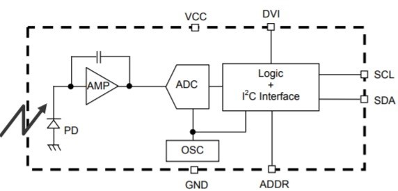
BH1750 is a Digital Ambient light sensor. It is easy to interface it with Arduino using I2C communication protocol. It consumes a very low amount of current. This sensor uses a photodiode to sense the light. This photodiode contains a PN junction. When light falls on it, electron-hole pairs are created in the depletion region. Due to the internal photoelectric effect, electricity is produced in the photodiode. This produced electricity is proportional to the intensity of light. This electricity is changed into a voltage by the Opamp. From the block diagram, PD is the photodiode which is used to sense the light. Its response is approximate to the human eye response.

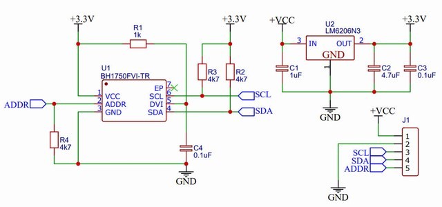
In BH1750 sensor an op-amp is an integrated circuit which converts the current from the photodiode into voltage. BH1750 uses an ADC to convert the analog values provided by AMP into digital values. The logic + I2C block shown in the block diagram is the unit where illuminance values are converted to LUX and the I2C communication process takes place. OSC is the internal clock oscillator of 320kHz, used as a clock for internal logic. BH1750 works with a supply voltage of 2.4V to 3.6V. BH1750FVI is the main module of the sensor which requires 3.3V for working. So, a voltage regulator is used in the circuit. SDA and SCL are the pins used for I2C communication. 4.7kΩ of pullup res istors are used with these pins.
There are three types of measurement modes
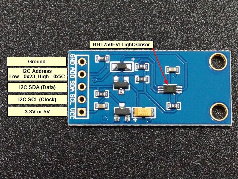
for BH1750. H-resolution mode2 takes 120ms for measurement and has an 0.5 lx of resolution. H-resolution mode also takes 120ms for measurement but its resolution is 1 lx. L- resolution takes 16ms for measurement and its resolution is 4 lx. H- resolution mode is more useful in darkness and it can also easily reject noise. There are 5 Pins on this sensor.
BH1750 Ambient Light Sensor interfacing to Arduino:
VCC & GND of BH1750 Ambient Light sensor is connected to 5 volts DC and ground of Arduino. SDA (Data) is connected to Analog input A5 of Arduino and SCL (Clock) is connected to Analog input A4 of Arduino. The green LED connected to Pin 2 will light up as soon as Arduino is switched on.
BH1750 Ambient Light Sensor interfacing to Node MCU:
VCC & GND of BH1750 Ambient Light sensor is connected to 3.3 volts DC and ground of Node MCU. SDA (Data) is connected to Pin GPIO4 of Node MCU and SCL (Clock) is connected to Pin GPIO5 of Node MCU. The green LED connected to Pin 2 will light up as soon as Node MCU is switched on.
BH1750 Ambient Light Sensor interfacing to ESP32:
VCC & GND of BH1750 Ambient Light sensor is connected to 3.3 volts DC and ground of ESP32. SDA (Data) is connected to Pin GPIO21 of ESP32 and SCL (Clock) is connected to Pin GPIO22 of ESP32. The green LED connected to Pin GPIO2 will light up as soon as ESP32 is switched on.
