DS1302 Real-Time Clock interfacing
with Arduino, Node MCU, ESP32 with LCD display
Real-time clock is a clock function used by systems that measure time even when the main device (such as MCU) is powered off. For example, even when the main battery or power supply is removed from a camera or gaming device, system can measure time by powering the real-time clock from a sub-battery or super capacitor built into that system.
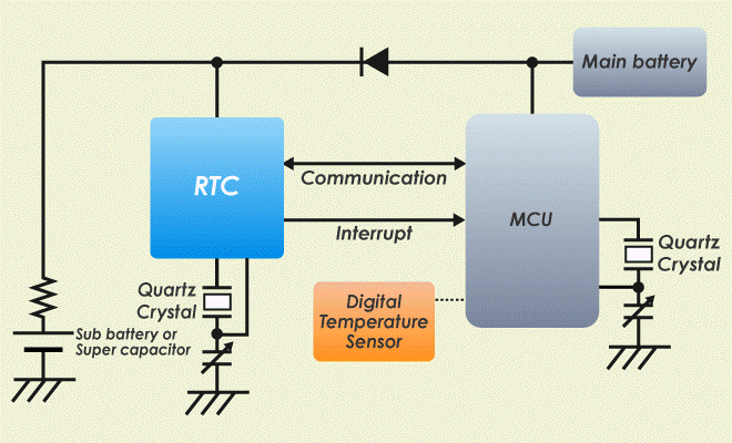
real-time clock achieves longer battery life by ultra-low current consumption. RTC has various time management solutions including high accuracy clock correction function, constant 32kHz output, expansion alarm, 24 bit up counter and ultra-small package.
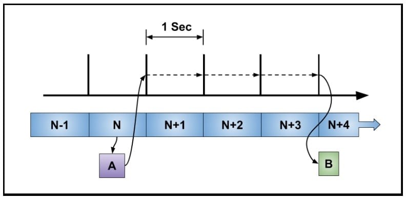
The real-time clock’s basic function is to produce intervals of one second and maintain a continuous count. You can see a representation of this in the diagram below. Also shown is a program function, A, reading a seconds counter and scheduling an event, B, to occur three seconds in the future. This action is called an alarm. Notice the seconds counter runs continuously and does not stop and start. Two primary requirements of an RTC are accuracy and continuous operation.
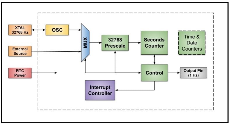
An RTC often has its own internal oscillator with an external crystal and an option to use an external frequency reference. All clock sources run at 32,768 Hz. An external clock source allows the use of a very accurate and stable device such as a TCXO (temperature-compensated crystal oscillator).
A clock source is selected with a multiplexer and input to a prescaler which divides the clock by a factor of 32,768 (215) to produce a one-second clock. A basic RTC has a seconds counter which is usually 32 bits or more. Some RTCs have specialized counters to keep track of the time of day and the calendar date.
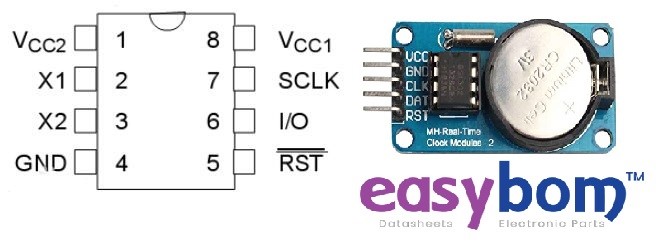
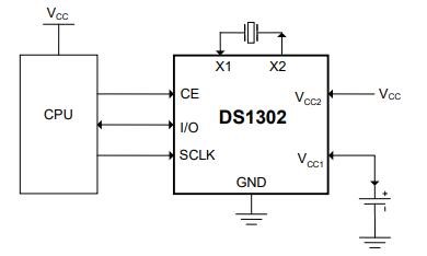
DS1302 is a low-power real-time clock chip with trickle current charging capability. It can time the year, month, day, week, hour, minute, and second, and has various functions such as leap year compensation. The DS1302 operates with very low power consumption and maintains data and clock information in less than 1mW. DS1302 is improved from DS1202 and adds the following features: dual power pins are used for the main power supply and backup power supply, Vcc1 is a programmable trickle charge power supply, and an additional seven bytes of memory are added. It uses an ordinary 32.768kHz crystal oscillator. The operating voltage is 2.0V~5.5V. DS1302 has a 31 × 8 RAM register for temporarily storing data.
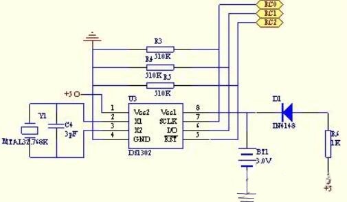
The pin arrangement of DS1302 is shown below, in which Vcc2 is the main power supply, and VCC1 is the backup power supply. It also keeps the clock running continuously even when the main power is turned off. The DS1302 is powered by the greater Vcc1 or Vcc2. When Vcc2 is greater than Vcc1, Vcc2 supplies power to DS1302. When Vcc2 is less than Vcc1, the DS1302 is powered by Vcc1. X1 and X2 are the oscillation sources, connected to a 32.768kHz crystal oscillator.
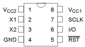
During power-up operation, RST must be kept low until Vcc>2.0V. RST can be set high only when SCLK is low. I/O is a serial data input and output terminal (bidirectional), which will be described in detail later. SCLK is the clock input.

The control byte of DS1302 is shown in Figure 2. The most significant bit (bit 7) of the control byte must be logic 1. If it is 0, data cannot be written into the DS1302. If bit 6 is 0, it means accessing the calendar clock data, and 1 means accessing RAM. Data; bit 5 to bit 1 indicate the address of the operation unit; if the least significant bit (bit 0) is 0, it means to perform a write operation, and if it is 1, it means to perform a read operation, and the control byte is always output from the lowest bit.
DS1302 has 12 registers, of which 7 registers are related to the calendar and clock. The data bits stored are in the form of BCD codes. The calendar, time registers, and their control words are shown in Table 1.
In addition, DS1302 has a year register, control register, charge register, clock burst register, and RAM-related registers. The clock burst register can sequentially read and write all register contents except the charge register at one time.
The registers related to RAM of DS1302 are divided into two categories: one is a single RAM unit, a total of 31, each unit is configured as an 8-bit byte, and its command control word is C0H~FDH, of which odd numbers are read operations, The even number is the write operation; the other type is the RAM register in the burst mode. In this mode, all 31 bytes of the RAM can be read and written at one time, and the command control words are FEH (write) and FFH (read).
DS1302 is a semi-SPI interface
At the rising edge of the next SCLK clock after the control instruction word is input, the data is written into the DS1302, and the data input starts from the low bit, that is, bit 0. Similarly, the data of DS1302 is read out on the falling edge of the next SCLK pulse following the 8-bit control command byte, and the data is read from low-order 0 to high-order 7. During data transfer from the DS1302’s clock calendar or RAM, the DS1302 must first send a command byte. If a single-byte transfer is performed, after the 8-bit command byte is transferred, the data byte is input on the rising edge of the next 2 SCLK cycles, or the data byte is output on the falling edge of the next 8 SCLK cycles.
DS1302 Real-Time Clock interfacing with Arduino:
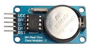
DS1302 Real-Time Clock has two power supplies. Main Power supply VCC & GND are connected to Arduino 5 volts DC and Ground pin. The secondary power supply is battery of 3 volts mounted on the board. There is a 32.768kHz crystal oscillator incorporated which provides accurate clock pulses. The CLK (Clock) be connected to Analog Pin A5, DAT (Data) is connected to Analog Pin A4. The display of time can be in any one of the forms.
DS1302 Real-Time Clock interfacing with Node MCU:
DS1302 Real-Time Clock has two power supplies. Main Power supply VCC & GND are connected to Node MCU 3.3 volts DC and Ground pin. The secondary power supply is battery of 3 volts mounted on the board. There is a 32.768kHz crystal oscillator incorporated which provides accurate clock pulses. The CLK (Clock) be connected to Pin SCL GPIO5, DAT (Data) is connected to SDA Pin GPIO4. The display of time can be in any one of the forms.
DS1302 Real-Time Clock interfacing with ESP32:
DS1302 Real-Time Clock has two power supplies. Main Power supply VCC & GND are connected to ESP32 3.3 volts DC and Ground pin. The secondary power supply is battery of 3 volts mounted on the board. There is a 32.768kHz crystal oscillator incorporated which provides accurate clock pulses. The CLK (Clock) be connected to Pin SCL GPIO22, DAT (Data) is connected to SDA Pin GPIO21. The display of time can be in any one of the forms.
