Japanese Solderless Terminal
Japanese Solderless Terminal (JST) connectors
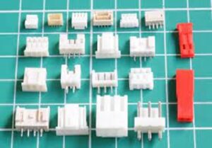
Japanese Solderless Terminal connectors in short known as JST connectors are excellent way of termination of copper cables for standardised productionising of electronics sub-systems which could give manufacturers to offer to their customers customised products by integrating numerous sub-systems JST connectors.
For example if you build microcontroller based sub-system with numerous 2 pin, 3 pin, 4 pin 5 pin JST sockets then depending on the sensor and other peripherals required by the customer you just needs to plug them into JST, test and deliver. This has greatly eased the production line where you could standardise to achieve high efficiency at the same time meet the customer requirements by plugging in all the sub components requested by customer.
J.S.T. Mfg. Co. (Japan Solderless Terminal) was invented in the year 1957 and since then it was used a slow profile may be due to IP rights held by JST. In the last couple of years this has flooded the market and is finding huge lot of applications due to its versatility. The product range has a huge collection of connectors in various configurations, different pitches, different sizes, different applications to every body’s budgetary needs.
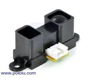
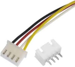
For the first time in the world Avinya-networks, Bangalore has introduced these products from JST range to meet school and college projects to totally avoid loose contacts, shorts, open circuits and frustration there off as well as guaranteed way of working to deliver consistent performance. The system developed by us works with Arduino, Node MCU ESP8266 as well as ESP32. It is totally plug and play and you can plug out once sensor and plug in another sensor without the need to do any soldering or precaution. The connectors shown here are male


connectors which are soldered on to the PCB with necessary connections. Most of the sensors these days come with built in JST connectors as shown. So if you wish to connect sensor to the microcontroller all that is required is to crimp the female connectors of appropriate pins on both sides of the JST compatible cable (Please note that only certain AWG-American Wire Gauge cables could be crimped on JST connectors using appropriate tool) and plug the cable into the sensor as well as to the microcontroller.
The same way you can have multiple LEDs to light for different indications, Buzzer to provide alarm conditions, relay connections, etc., all can be crimped with JST connectors with built in current limiting resistors heat shrunk so that all peripheral devices are plug and play. When you want to change colour of LED say from Green to Red, just plug out Green and plug in Red. All necessary connections are already taken care with the microcontrollers on the PCB.
With JST connectors the identification of fault is far easier. Plug out all the external components, then start plugging in one by one you will be able to identify the fault. You can also interchange the components so that if you plug the defective component from one port to another if it still does not work you are the component is defective.
