EM18 RFID reader of frequency 125 kHz interface
with Arduino, Node MCU, ESP32

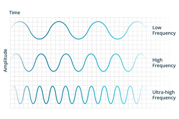
RFID systems are often categorized by their operating frequency band. If an RFID system operates at a lower frequency, it has a slower data read rate, but increased capabilities for reading near or on metal or liquid surfaces. The LF band covers frequencies from 30 KHz to 300 KHz. Typically LF RFID systems operate at 125 KHz, although there are some that operate at 134 KHz. This frequency band provides a short read range of 10 cm, and has slower read speed than the higher frequencies, but is not very sensitive to radio wave interference.

RFID stands for Radio Frequency Identification. Each RFID card has a unique ID embedded in it and a RFID reader is used to read the RFID card number. Energy Flows from Antenna to Tag (And back). The propagated waves travel in space to a distance vertically and horizontally based on the specific gain and beamwidth parameters of the antenna.
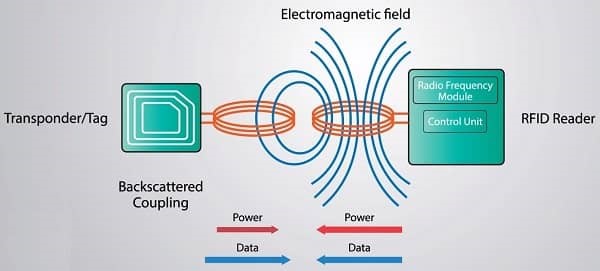
The RFID tags in the field receive the energy, or RF waves, using their own antennas. The energy received travels through the RFID tag’s antenna and a portion of it is used to activate the chip (the Integrated Circuit, or IC) and prepare for transmission of data based on commands received from the RFID reader.

When the chip is turned on, it modulates the energy with the information stored in the tag (pertinent to the reader’s request) and “reflects” the remaining energy back. This information could be EPC memory, User Memory, or anything programmed on the tag. This reflection of energy back to the antenna is known as backscatter radiation.
The main differences between EM-18 and RC522 RFID Modules are EM-18 is based on 125 KHz Radio Frequency Communication while the RC522 is based on 13.56 MHz Frequency. Coming to the interface options, EM-18 uses Serial Communication whereas RC522 uses SPI Communication (although the chip supports I2C and UART as well).

EM18 is a RFID reader which is used to read RFID tags of frequency 125 kHz. After reading tags, it transmits unique ID serially to the PC or microcontroller using UART communication or Wiegand format on respective pins. EM18 RFID reader reads the data from RFID tags which contains stored ID which is of 12 bytes.
An RFID or radio frequency identification system consists of two main components, a tag attached to the object to be identified, and a reader that reads the tag.
A reader consists of a radio frequency module and an antenna that generates a high frequency electromagnetic field. Whereas the tag is usually a passive device (it does not have a battery). It consists of a microchip that stores and processes information, and an antenna for receiving and transmitting a signal.
When the tag is brought close to the reader, the reader generates an electromagnetic field. This causes electrons to move through the tag’s antenna and subsequently powers the chip.
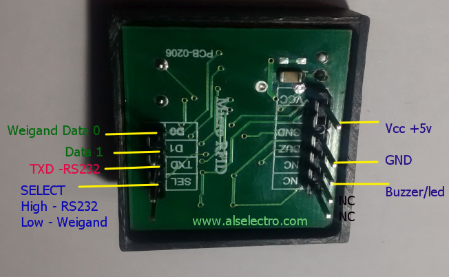
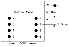
The chip then responds by sending its stored information back to the reader in the form of another radio signal. This is called a backscatter. The reader detects and interprets this backscatter and sends the data to a computer or microcontroller. EM18 does not support I2C or SPI interface. It supports WIEGAND and RS232 protocols. Pin 4 and Pin 5 of EM18 are not used. Pin 6 of EM18 viz., SEL is used for selecting RS232 or Wiegand protocol. If this is High RS232 is selected and if low Wiegand is selected.


EM18 RFID reader of frequency 125 kHz interface with Arduino:
VCC and GND Pins of the EM18 board are connected to 5 volts DC and ground pins of Arduino. Pin 3 of EM18 is for providing beep and LED whenever the card is brought close to reader. This pin 3 can be connected to Pin 7 of the Arduino board which in turn will trigger Pin 3 for Red LED switching and Pin 4 for buzzer switching. Pin 7 of EM18 is Tx pin connected to Rx pin of Arduino because this pin transmits data with RS232 protocol. Pin 8 and Pin 9 of EM18 are Wiegand communication pins connected to Arduino Data 1 and Data 0 respectively. Green LED is connected to Pin 2 of Arduino to indicate the Power On. When reader reads and finds the card authorised for entry, the relay operates and door lock opens this is initiated by Pin 12 High.
EM18 RFID reader of frequency 125 kHz interface with Node MCU:
VCC and GND Pins of the EM18 board are connected to 3.3 volts DC and ground pins of Node MCU. Pin 3 of EM18 is for providing beep and LED whenever the card is brought close to reader. This pin 3 can be connected to Pin GPIO7 of the Node MCU board which in turn will trigger Pin GPIO3 for Red LED switching and Pin GPIO4 for buzzer switching. Pin 7 of EM18 is Tx pin connected to Rx pin of Node MCU because this pin transmits data with RS232 protocol. Pin 8 and Pin 9 of EM18 are Wiegand communication pins connected to Node MCU Data 1 and Data 0 respectively. Green LED is connected to Pin GPIO2 of Node MCU to indicate the Power On. When reader reads and finds the card authorised for entry, the relay operates and door lock opens this is initiated by Pin GPIO12 High.
EM18 RFID reader of frequency 125 kHz interface with ESP32:
VCC and GND Pins of the EM18 board are connected to 3.3 volts DC and ground pins of ESP32. Pin 3 of EM18 is for providing beep and LED whenever the card is brought close to reader. This pin 3 can be connected to Pin GPIO7 of the ESP32 board which in turn will trigger Pin GPIO3 for Red LED switching and Pin GPIO4 for buzzer switching. Pin 7 of EM18 is Tx pin connected to Rx pin of ESP32 because this pin transmits data with RS232 protocol. Pin 8 and Pin 9 of EM18 are Wiegand communication pins connected to ESP32 Data 1 and Data 0 respectively. Green LED is connected to Pin GPIO2 of ESP32 to indicate the Power On. When reader reads and finds the card authorised for entry, the relay operates and door lock opens this is initiated by Pin GPIO12 High.
