PN532 Near-field communication (NFC) RFID Module interface
with Arduino, Node MCU, ESP32
RFID stands for Radio Frequency Identification. Each RFID card has a unique ID embedded in it and a RFID reader is used to read the RFID card number. Energy Flows from Antenna to Tag (And back). The propagated waves travel in space to a distance vertically and horizontally based on the specific gain and beamwidth parameters of the antenna.
Near Field Communication (NFC) is a technology standard based on Radio Frequency Identification (RFID), transmitting information wirelessly over short distances.

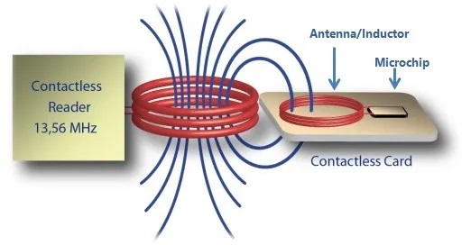
NFC operates on the principle of inductive coupling, at least for short-range implementations. This essentially involves the reader device generating a magnetic field by passing an electric current through a coil. When a tag (with its own coil) is brought nearby, the field induces an electric current within the tag — sans any wires or even physical contact. Then, once the initial handshake is complete, any stored data on the tag is wirelessly transmitted to the reader.


The RFID tags in the field receive the energy, or RF waves, using their own antennas. The energy received travels through the RFID tag’s antenna and a portion of it is used to activate the chip (the Integrated Circuit, or IC) and prepare for transmission of data based on commands received from the RFID reader.
When the chip is turned on, it modulates the energy with the information stored in the tag (pertinent to the reader’s request) and “reflects” the remaining energy back. This information could be EPC memory, User Memory, or anything programmed on the tag. This reflection of energy back to the antenna is known as backscatter radiation.
An RFID or radio frequency identification system consists of two main components, a tag attached to the object to be identified, and a reader that reads the tag.
A reader consists of a radio frequency module and an antenna that generates a high frequency electromagnetic field. Whereas the tag is usually a passive device (it does not have a battery). It consists of a microchip that stores and processes information, and an antenna for receiving and transmitting a signal.
When the tag is brought close to the reader, the reader generates an electromagnetic field. This causes electrons to move through the tag’s antenna and subsequently powers the chip.
The chip then responds by sending its stored information back to the reader in the form of another radio signal. This is called a backscatter. The reader detects and interprets this backscatter and sends the data to a computer or microcontroller.
PN532 is capable of NFC (Near Field Communication) which means it can share data with other devices within a range of 4 centimetres. Near-field communication (NFC) is a short-range wireless connectivity technology that uses magnetic field induction to enable communication between devices when they’re touched together or brought within a few centimetres of each other.
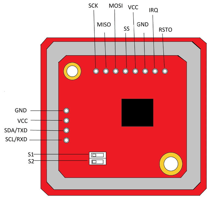
PN532 has both I2C and SPI interface. We will try to connected it to Arduino using SPI as well as I2C interface. There can be two different types of tones one type when it is successfully and another type when reader fails to read the tag.

PN532 Near-field communication (NFC) RFID Module interface with Arduino:
VCC and GND of the PN532 are connected to 5 volts supply and ground pins of Arduino. SCK (Clock), MISO (Slave out), MOSI (Slave In), SS (Chip Select) of PN532 are connected to Pin 11, Pin 12, Pin 13 and Pin 10 of Arduino respectively. All the actions such as access permitted, access denied etc., are displayed on LCD display which is connected to Arduino using I2C bus.
Green LED is connected to Pin 2 of Arduino to indicate the Power On. The Red LED and buzzer are connected to Pin 3 and Pin 4 or Arduino. Red LED and buzzer will turn on whenever the access Tag is read by PN532 as a signal to the user.
PN532 Near-field communication (NFC) RFID Module interface with ESP32:
VCC and GND of the PN532 are connected to 3.3 volts supply and ground pins of ESP32. SCK (Clock), MISO (Slave out), MOSI (Slave In), SS (Chip Select) of PN532 are connected to Pin GPIO11, Pin GPIO12, Pin GGPIO13 and Pin GPIO10 of ESP32 respectively. All the actions such as access permitted, access denied etc., are displayed on LCD display which is connected to Node MCU using I2C bus.
Green LED is connected to Pin GPIO2 of ESP32 to indicate the Power On. The Red LED and buzzer are connected to Pin 3 and Pin 4 ESP32. Red LED and buzzer will turn on whenever the access Tag is read by PN532 as a signal to the user.
Green LED is connected to Pin 2 of Arduino to indicate the Power On. The Red LED and buzzer are connected to Pin 3 and Pin 4 or Arduino. Red LED and buzzer will turn on whenever the access Tag is read by PN532 as a signal to the user.
