YFS201 Hall Effect Water Flow Sensor Interfacing
with Arduino, Node MCU, ESP32 with OLED
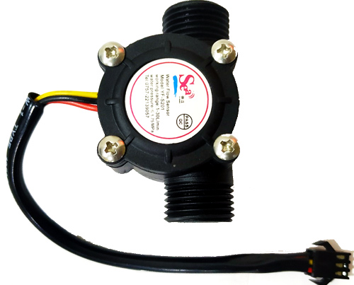
Chemical industries have to constantly measure and quantify the liquids that they are handling during this automation process, and the most common sensor used to measure the flow of a liquid is a Flow Sensor. By using a flow sensor with a microcontroller like Arduino, we can calculate the flow rate, and check the volume of liquid that has passed through a pipe, and control it as required. A water flow sensor will be a good addition to projects like Automatic Water Dispenser and Smart Irrigation Systems where we need to monitor and control the flow of liquids. We will interface the water flow sensor with Arduino and LCD, and program it to display the volume of water, which has passed through the valve.


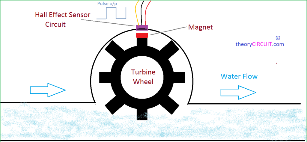
The Water Flow Sensor for Flow Rate & Volume Measurement using Arduino works on the principle of the Hall effect. According to the Hall effect, a voltage difference is induced in a conductor transverse to the electric current and the magnetic field perpendicular to it. Here, the Hall effect is utilized in the flow meter using a small fan/propeller-shaped rotor, which is placed in the path of the liquid flowing.
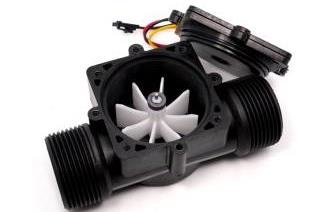
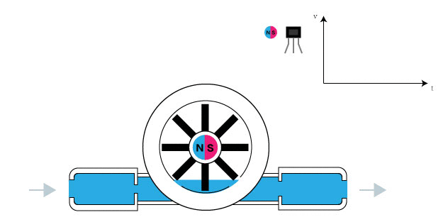
The liquid pushes against the fins of the rotor, causing it to rotate. The shaft of the rotor is connected to a Hall effect sensor. It is an arrangement of a current flowing coil and a magnet connected to the shaft of the rotor, thus a voltage/pulse is induced as this rotor rotates. In this flow meter, for every liter of liquid passing through it per minute, it outputs about 4.5 pulses. This is due to the changing magnetic field caused by the magnet attached to the rotor shaft. We measure the number of pulses using an Arduino and then calculate the flow rate in liters per hour (L/hr) and total volume in Litre using a simple conversion formula
In many large scale manufacturing companies, the first thing you will notice is that they are all automated. Soft Drink Industries and Chemical industries have to constantly measure and quantify the liquids that they are handling during this automation process, and the most common sensor used to measure the flow of a liquid is a Flow Sensor. By using a flow sensor with a microcontroller like Arduino, we can calculate the flow rate, and check the volume of liquid that has passed through a pipe, and control it as required. Apart from manufacturing industries, flow sensors can also be found in the agriculture sector, food processing, water management, mining industry, water recycling, coffee machines, etc. Further, a water flow sensor will be a good addition to projects like Automatic Water Dispenser and Smart Irrigation Systems where we need to monitor and control the flow of liquids.
YFS201 Hall Effect Water Flow Sensor Interfacing with Arduino:
There are only three terminals for water flow sensor. VCC and GND are connected to 5 volts DC and ground respectively to Arduino. Output pulse terminal is connected to pin 7 of Arduino which will count the pulses and arrive at the flow rate and volume of water. Pin 7 will trigger Pin 3 & Pin 4 which are connected to Red LED and Buzzer respectively to indicate that there is water flowing or it can be given the other way like when water flow stops. Green LED is connected to Pin 2 which indicates that the Arduino is on.
YFS201 Hall Effect Water Flow Sensor Interfacing with Node MCU:
There are only three terminals for water flow sensor. VCC and GND are connected to 3.3 volts DC and ground respectively to Node MCU. Output pulse terminal is connected to pin 7 of Node MCU which will count the pulses and arrive at the flow rate and volume of water. Pin 7 will trigger Pin 3 & Pin 4 which are connected to Red LED and Buzzer respectively to indicate that there is water flowing or it can be given the other way like when water flow stops. Green LED is connected to Pin 2 which indicates that the Node MCU is on.
YFS201 Hall Effect Water Flow Sensor Interfacing with ESP32:
There are only three terminals for water flow sensor. VCC and GND are connected to 3.3 volts DC and ground respectively to ESP32. Output pulse terminal is connected to pin 7 of ESP32 which will count the pulses and arrive at the flow rate and volume of water. Pin 7 will trigger Pin 3 & Pin 4 which are connected to Red LED and Buzzer respectively to indicate that there is water flowing or it can be given the other way like when water flow stops. Green LED is connected to Pin 2 which indicates that the ESP32 is on.
