Measuring water Flow Rate and Volume using Hall effect sensor Interfaced
with Arduino, Node MCU and ESP32
Chemical industries have to constantly measure and quantify the liquids that they are handling during this automation process, and the most common sensor used to measure the flow of a liquid is a Flow Sensor. By using a flow sensor with a microcontroller like Arduino, we can calculate the flow rate, and check the volume of liquid that has passed through a pipe, and control it as required. A water flow sensor will be a good addition to projects like Automatic Water Dispenser and Smart Irrigation Systems where we need to monitor and control the flow of liquids. We will interface the water flow sensor with Arduino and LCD, and program it to display the volume of water, which has passed through the valve.


Working Principle: Hall Effect Sensors consist basically of a thin piece of rectangular p-type semiconductor material such as gallium arsenide (GaAs), indium antimonide (InSb) or indium arsenide (InAs) passing a continuous current through itself. When the device is placed within a magnetic field, the magnetic flux lines exert a force on the semiconductor material which deflects the charge carriers, electrons and holes, to either side of the semiconductor slab. This movement of charge carriers is a result of the magnetic force they experience passing through the semiconductor material.

The effect of generating a measurable voltage by using a magnetic field is called the Hall Effect after Edwin Hall who discovered it back in the 1870’s with the basic physical principle underlying the Hall effect being Lorentz force. To generate a potential difference across the device the magnetic flux lines must be perpendicular, (90o) to the flow of current and be of the correct polarity, generally a south pole. The Hall effect provides information regarding the type of magnetic pole and magnitude of the magnetic field. For example, a south pole would cause the device to produce a voltage output while a north pole would have no effect. Generally, Hall Effect sensors and switches are designed to be in the “OFF”, (open
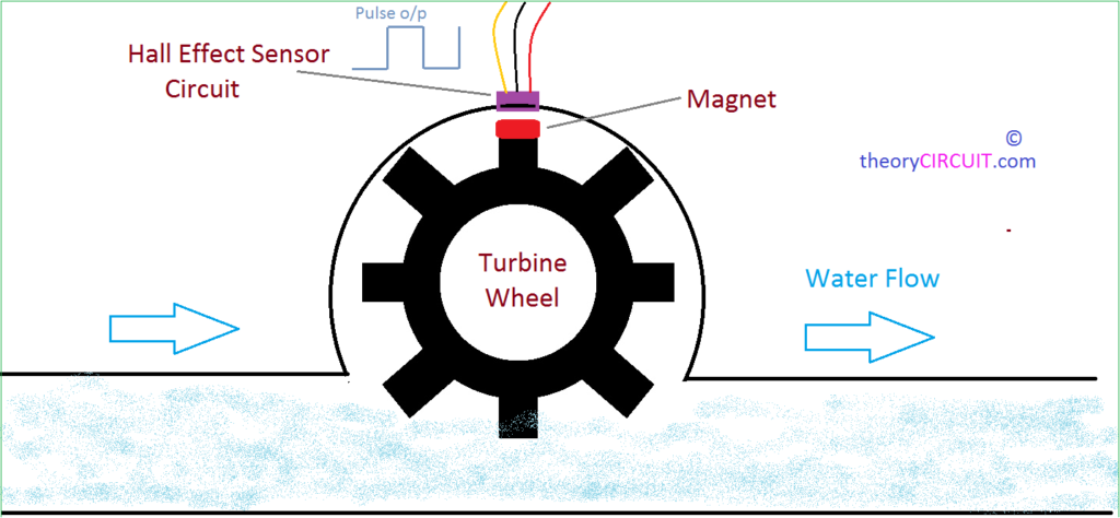
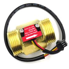
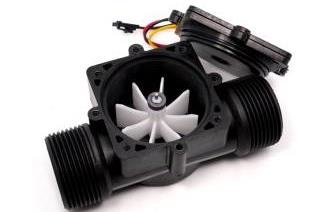
The water flow sensor is integrated with a magnetic hall effect sensor, which generates an electric pulse with every revolution. Its design is in such a way that the hall effect sensor is sealed off from the water, and allows the sensor to stay safe and dry. These pulses are available on Yellow wire. The water flow sensor consists of a pinwheel sensor that measures the quantity of liquid that has passed through it.
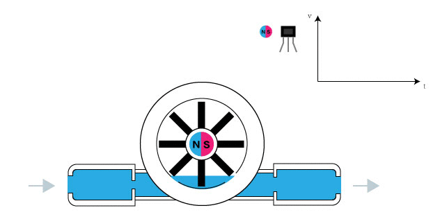
The maximum current it draws at 5V is 15mA, and the working flow rate is 1 to 30 liters/minute. When the liquid flows through the sensor, it makes contact with the fins of the turbine wheel, which is placed in the path of the flowing liquid. The shaft of the turbine wheel is connected to a hall effect sensor. Due to this, whenever water flows through the valve it generates pulses.
Now, all we have to do is to measure the time for the pluses or to count the number of pulses in 1 second and then calculate the flow rates in liter per hour (L/Hr) and then use simple conversion formula to find the volume of the water which had passed through it. To measure the pulses, we are going to use micro-controlle
Measuring water Flow Rate and Volume using Hall effect sensor Interfaced with Arduino:
The sensor has 3 wires RED, YELLOW, and BLACK as shown in the figure. The red wire is used for supply voltage of 5 volts from Arduino and the black wire is connected to GND pin of Arduino. The yellow wire is used for output (pulses), which can be read by Arduino. This is connected to pin 7 of Arduino.
Apart from this we need to connect two LEDs and one Buzzer into Arduino circuit to give us critical information. Green LED is connected to Pin 2 of the Arduino which turns on whenever the Arduino is switched on to indicate power on. The Red LED and Buzzer is connected to Pin 3 and Pin 4 of Arduino. Both will turn on whenever the Pin 7 goes Low indicating the flow of water has stopped.
Measuring water Flow Rate and Volume using Hall effect sensor Interfaced with Node MCU:
The sensor has 3 wires RED, YELLOW, and BLACK as shown in the figure. The red wire is used for supply voltage of 3.3 volts from Node MCU and the black wire is connected to GND pin of Node MCU. The yellow wire is used for output (pulses), which can be read by Node MCU. This is connected to pin GPIO7 of Node MCU.
Apart from this we need to connect two LEDs and one Buzzer into Node MCU circuit to give us critical information. Green LED is connected to Pin GPIO2 of the Node MCU which turns on whenever the Node MCU is switched on to indicate power on. The Red LED and Buzzer is connected to Pin GPIO3 and Pin GPIO4 of Node MCU. Both will turn on whenever the Pin GPIO7 goes Low indicating the flow of water has stopped.
Measuring water Flow Rate and Volume using Hall effect sensor Interfaced with ESP32:
The sensor has 3 wires RED, YELLOW, and BLACK as shown in the figure. The red wire is used for supply voltage of 3.3 volts from ESP32 and the black wire is connected to GND pin of ESP32. The yellow wire is used for output (pulses), which can be read by ESP32. This is connected to pin GPIO7 of ESP32.
Apart from this we need to connect two LEDs and one Buzzer into ESP32 circuit to give us critical information. Green LED is connected to Pin GPIO2 of the ESP32 which turns on whenever the ESP32 is switched on to indicate power on. The Red LED and Buzzer is connected to Pin GPIO3 and Pin GPIO4 of ESP32. Both will turn on whenever the Pin GPIO7 goes Low indicating the flow of water has stopped.
