Hall Effect Sensor interfacing
with Arduino, Node MCU, ESP32

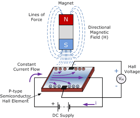
The principle of the Hall effect states that when a current-carrying conductor or a semiconductor is introduced to a perpendicular magnetic field, a voltage can be measured at the right angle to the current path. This effect of obtaining a measurable voltage is known as the Hall effect. The Hall effect was discovered by Edwin Herbert Hall in 1879.
Hall-effect sensors are the linear transducers that are used to measure the magnitude of the magnetic field. Working on the principle of Hall Effect, these sensors generate a Hall voltage when a magnetic field is detected, which is used to measure the magnetic flux density.

Rotating machinery requires speed sensing for functional systems such as control, monitoring, and safety. To ensure safe operation, it is especially important to monitor rotor speeds in turbine engines. The inductive sensor also known as magnetic pickup sensor during the operation work, due to inductive effect, The sensor’s coil is producing the oscillating voltage.( one kind of sinusoidal waveform signal (∼) AC voltage).
Unlike inductive sensors, the output signal from a Hall Effect sensor is not affected by the rate of change of the magnetic field. The produced output voltage typically is in the range of mV and is additionally amplified by integrated electronics, fitted inside of the sensor housing.
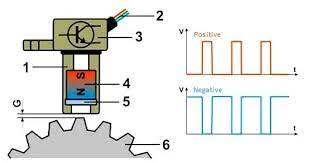
Figure shows a typical build of a Hall Effect sensor. The final output voltage signal usually is in digital waveform pulses (square form). The output signal of the sensor can be either positive or negative with peak voltage usually up to 5 V or 12 V, depending upon the type of the integrated electronics and requirements of the used system. The amplitude of the output signal remains constant, only the frequency increases proportionally with rpm. Unlike inductive sensors which generate a voltage signal by itself, the Hall Effect sensors must be additionally supplied by external voltage needed for integrated electronics. The usual supplying voltage (+Vcc) is mainly 5 V but in some cases can be 12 V.
- Sensor Housing
- Output wires (+Vcc, −Vcc and signal)
- Integrated electronics
- Permanent magnet
- Hall Effect device
- Trigger wheel
- Air gap

Based on the relation between hall voltage and magnetic flux density, Hall Effect sensors are of two types. In the linear sensor, the output voltage is linearly related to magnetic flux density. In the threshold sensor, at each magnetic flux density, the output voltage will have a sharp decrease. These are two main types of hall-effect sensors, one which gives an Analog output and the other which gives a digital output.
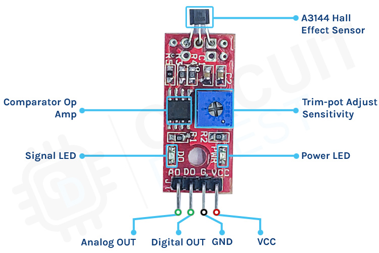
A3144 is a digital output hall sensor, meaning if it detects a magnet field the output will go low else the output will remain high.

The Hall effect sensor device shown here has four pins and includes an on-chip Hall voltage generator for magnetic sensing, a comparator that amplifies the Hall voltage, and a Schmitt trigger to provide switching hysteresis for noise rejection, and open-collector output. An internal bandgap regulator is used to provide temperature compensated supply voltage for internal circuits and allows a wide operating supply range. If a magnetic flux density larger than threshold Bop, the output is turned on (low). The output state is held until a magnetic flux density reversal falls below Bop causing the output to be turned off (high).
Hall effect sensors are made of semiconductor substances like gallium arsenide (GaAs), indium arsenide (InAs), indium antimonide (InSb), indium phosphide, or graphene. A constant DC supply is provided for the hall effect sensors to work.
Hall effect sensor when it comes in contact with magnetic field Hall voltage will be induced in the sensor which would be amplified and made available as Analog OUT which can be connected to A0 pin of Arduino board where A0 has ADC (Analog to Digital Converter) of 10bit accuracy the value so obtained can be displayed on LCD display. At present LCD is not connected but can be provided.
On the Hall effect sensor board the amplified voltage will be also fed to comparator and using trim pot the output voltage can be triggered into square wave which will be connected Arduino board.
Hall Effect Sensor interfacing with Arduino:
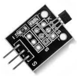
Hall Effect sensors are available in 3 pin and 4 Pin version.
3 Pin Version: VCC & GND are connected to 5 volts DC and ground pins of Arduino. The third Pin Signal is connected to any Digital Pin of Arduino say Pin 7 which in turn will trigger Pin 9 to be high.
4 Pin version: VCC & GND are connected to 5 volts DC and ground pins of Arduino. Dout is connected to Pin 7 which will trigger Pin 7 go high. Aout is connected Analog Pin A0 of Arduino. Apart from this we need to connect two LEDs and one Buzzer into Arduino circuit to give us critical information. Green LED is connected to Pin 2 of the Arduino which turns on whenever the Arduino is switched on to indicate power on. The Red LED and Buzzer is connected to Pin 3 and Pin 4 of Arduino. Both will turn on whenever the Pin 7 goes high indicating there is positive Hall effect detected.
Hall Effect Sensor interfacing with Node MCU:
Hall Effect sensors are available in 3 pin and 4 Pin version.
3 Pin Version: VCC & GND are connected to 3.3 volts DC and ground pins of Node MCU. The third Pin Signal is connected to any Digital Pin of Node MCU say Pin GPIO7 which in turn will trigger Pin GPIO9 to be high.
4 Pin version: VCC & GND are connected to 3.3 volts DC and ground pins of Node MCU. Dout is connected to Pin GPIO7 which will trigger Pin GPIO7 go high. Aout is connected Analog Pin ADC0 of Node MCU. Apart from this we need to connect two LEDs and one Buzzer into Node MCU circuit to give us critical information. Green LED is connected to Pin GPIO2 of the Node MCU which turns on whenever the Node MCU is switched on to indicate power on. The Red LED and Buzzer is connected to Pin GPIO3 and Pin GPIO4 of Node MCU. Both will turn on whenever the Pin GPIO7 goes high indicating there is positive Hall effect detected.
Hall Effect Sensor interfacing with ESP32:
Hall Effect sensors are available in 3 pin and 4 Pin version.
3 Pin Version: VCC & GND are connected to 3.3 volts DC and ground pins of ESP32. The third Pin Signal is connected to any Digital Pin of ESP32 say Pin GPIO7 which in turn will trigger Pin GPIO9 to be high.
4 Pin version: VCC & GND are connected to 3.3 volts DC and ground pins of ESP32. Dout is connected to Pin GPIO7 which will trigger Pin GPIO7 go high. Aout is connected Analog Pin ADC0 of ESP32. Apart from this we need to connect two LEDs and one Buzzer into ESP32 circuit to give us critical information. Green LED is connected to Pin GPIO2 of the ESP32 which turns on whenever the ESP32 is switched on to indicate power on. The Red LED and Buzzer is connected to Pin GPIO3 and Pin GPIO4 of ESP32. Both will turn on whenever the Pin GPIO7 goes high indicating there is positive Hall effect detected.
