INA219 Current Sensor Interfacing
with Arduino, Node MCU, ESP32 with display

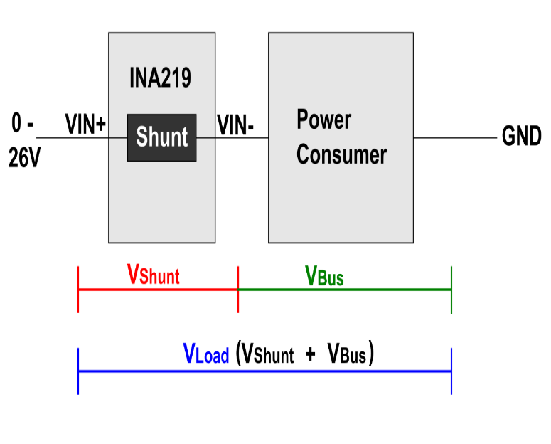
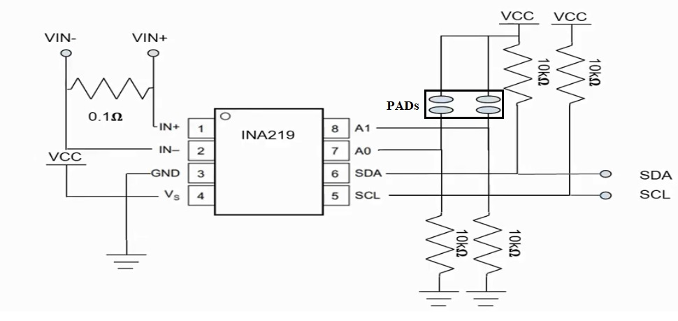
The INA219 chip at the core of the dc current sensor module is a current shunt and power monitor with an I2C or SMBUS (System Management Bus predecessor or I2C and it inter-operates with I2C) compatible interface. It features 16 programmable addresses. The chip uses a single 3 to 5.5V supply, drawing a maximum of 1mA of supply current. The INA219 chip can monitor both the shunt voltage drop and the bus supply voltage, with programmable conversion times and filtering. A programmable calibration value, combined with an internal multiplier, enables direct readouts of current in amperes.

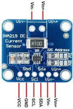
An additional multiplying register calculates power in watts. The DC current in the circuit is measured by connecting the circuit in series with Vin+ and Vin-. R100 is the precision shunt resistor which develops voltage proportional to current in the main circuit.
When we want to measure DC current in any circuit the + of circuit is connected to Vin + (maximum 26 volts) and from Vin- we can continue the circuit to which load is connected. A precision amplifier measures the voltage across the 0.1 ohm, 1% accurate resistor. Since the amplifier maximum input difference is ±320mV this means it can measure up to ±3.2 Amps. With the internal 12bit ADC, the resolution at ±3.2A range is 0.8mA.

With the internal gain set at the minimum of div8, the max current is ±400mA and the resolution is 0.1mA. Advanced hackers can remove the 0.1ohm current sense resistor and replace it with their own to change the range (say a 0.01 ohm to measure up 32 Amps with a resolution of 8mA). INA219 communicates with Arduino, Node MCU or ESP32 on I2C bus which is capable of addressing 128 devices being a 7bit addressing scheme. MCU would send first the address bit of the slave with 1 bit that indicates whether MCU wants to send data or receive data.
INA219 Current Sensor Interfacing with Arduino with display
The VCC and GND of this module are connected to 5 volts DC and Ground Pin of Arduino respectively. The SDA (Data) and SCL (Clock) Pins of the module are connected to SDA and SCL Pins of Arduino.
There is a Green LED connected to Pin 2 of Arduino which lights up when Arduino is powered up. There is Red LED and buzzer which can be triggered when the current measured by sensor exceeds limits set by us. This LED and buzzer are connected to Pin 3 and Pin 4 of Arduino. Both LEDs are provided with 220 ohms current limiting resistors which are ultimately connected to Ground Pin.
INA219 Current Sensor Interfacing with Node MCU with display
The VCC and GND of this module are connected to 3.3 volts DC and Ground Pin of Arduino respectively. The SDA (Data) and SCL (Clock) Pins of the module are connected to SDA GPIO4 and SCL GPIO5 Pins of Node MCU.
There is a Green LED connected to Pin GPIO2 of Node MCU which lights up when Node MCU is powered up. There is Red LED and buzzer which can be triggered when the current measured by sensor exceeds limits set by us. This LED and buzzer are connected to Pin GPIO3 and Pin GPIO4 of Node MCU. Both LEDs are provided with 220 ohms current limiting resistors which are ultimately connected to Ground Pin.
INA219 Current Sensor Interfacing with ESP32 with display
The VCC and GND of this module are connected to 3.3 volts DC and Ground Pin of Arduino respectively. The SDA (Data) and SCL (Clock) Pins of the module are connected to SDA GPIO21 and SCL GPIO22 Pins of ESP32.
There is a Green LED connected to Pin GPIO2 of ESP32 which lights up when Arduino is powered up. There is Red LED and buzzer which can be triggered when the current measured by sensor exceeds limits set by us. This LED and buzzer are connected to Pin GPIO3 and Pin GPIO4 of ESP32. Both LEDs are provided with 220 ohms current limiting resistors which are ultimately connected to Ground Pin.
