SW-520 Shock Tilt Vibration Sensor SW-18010P KY-002 Interfacing
with Arduino, Node MCU, ESP32

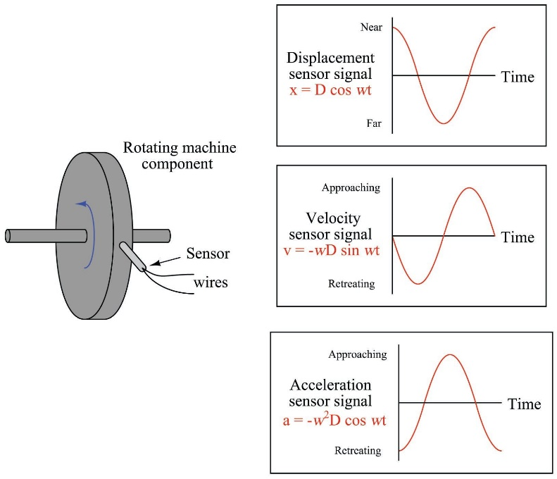
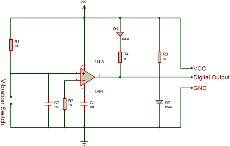
Whenever any machine is installed on the bed and coupled to any other machine or equipment there are varity of mis-alignments which cause vibration which can be detected by mounting different types of sensors at shaft, body, bed etc., This sensor SW-420 sensor is a simple tilt sensor and it does not analyse or detect vibration Axis wise for which you need to select a different one. This sensor is general purpose Vibration sensor which has a popular comparator LM393 and whenver the value of vibration is more than the set value the comparator triggers a square value output using Schimitt trigger and Red LED will be lit and simultaneously buzzer starts making sound.

Vibration switch recognizes the amplitude of the vibration to which it is exposed. The switch response can be electrical contact closure or contact opening. The electrical contact may be either an electromechanical relay or a solid-state device.
Whenever any machine is installed on the bed and coupled to any other machine or equipment there are varity of mis-alignments which cause vibration which can be detected by mounting this sensor on the shaft or the body. It does not analyse or detect vibration Axis wise for which you need to select a different one. This sensor is general purpose Vibration sensor which has a popular comparator LM393 and whenver the value of vibration is more than the set value the comparator triggers a square value output using Schimitt trigger and Red LED will be lit and simultaneously buzzer starts making sound.


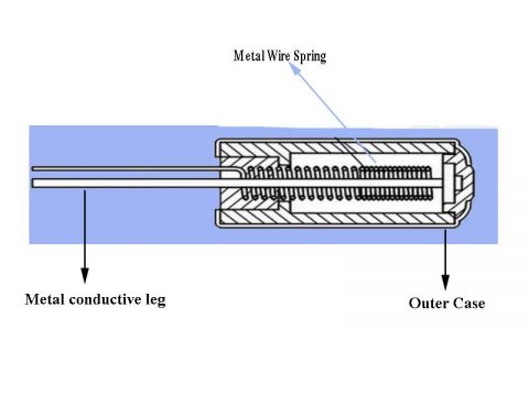
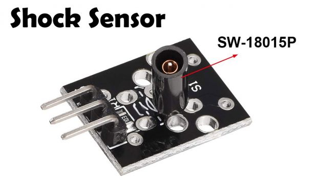
Inside of the sensor we have a thin metal wire spring that is around a metal conductive leg and around all this we have the outer case. The metal conductive wire is connected to five volts and around the solid wire is a springform wire, it is very thin and when there is a vibration the spring will hit the solid and then the five volts will go through the spring and then the Arduino will read different in voltage and give our signal. So now if we shake the sensor the thin metal spring and the metal conductive leg will touch each other and the current will flow from the metal conductive leg to the thin metal wire spring. We will then have a potential of 5 volts and with this, we can detect a shaking or a vibration. The shock sensor is this component on the module the shape of this sensor looks like a cylindrical capacitor in which we have a 10-kilo ohm resistor.
SW-520 Shock Tilt Vibration Sensor SW-18010P KY-002 Interfacing with Arduino:
SW-520 Shock Tilt Vibration Sensor SW-18010P KY-002 has three pins of which VCC & GND are connected to 5 volts DC and ground pins of Arduino. Third pin D0 output is connected to one of the digital pins let us say Pin 7 of Arduino which when triggered will trigger Pin 3 and Pin 4 of Arduino as well as Pin 8 which could be used for some action down stream. Pin 3 is connected to Red LED and Pin 4 connected to buzzer which will turn on whenever the shock, vibration detected. Pin 2 is connected to Green LED which will turn on as soon as Arduino is switched on to indicate power on condition.
SW-520 Shock Tilt Vibration Sensor SW-18010P KY-002 Interfacing with Node MCU:
SW-520 Shock Tilt Vibration Sensor SW-18010P KY-002 has three pins of which VCC & GND are connected to 3.3 volts DC and ground pins of Node MCU. Third pin D0 output is connected to one of the digital pins let us say Pin GPIO7 of Node MCU which when triggered will trigger Pin GPIO3 and Pin GPIO4 of Node MCU as well as Pin GPIO8 which could be used for some action down stream. Pin GPIO3 is connected to Red LED and Pin GPIO4 connected to buzzer which will turn on whenever the shock, vibration detected. Pin GPIO2 is connected to Green LED which will turn on as soon as Node MCU is switched on to indicate power on condition.
SW-520 Shock Tilt Vibration Sensor SW-18010P KY-002 Interfacing with ESP32:
SW-520 Shock Tilt Vibration Sensor SW-18010P KY-002 has three pins of which VCC & GND are connected to 3.3 volts DC and ground pins of ESP32. Third pin D0 output is connected to one of the digital pins let us say Pin GPIO7 of ESP32 which when triggered will trigger Pin GPIO3 and Pin GPIO4 of ESP32 as well as Pin GPIO8 which could be used for some action down stream. Pin GPIO3 is connected to Red LED and Pin GPIO4 connected to buzzer which will turn on whenever the shock, vibration detected. Pin GPIO2 is connected to Green LED which will turn on as soon as ESP32 is switched on to indicate power on condition.
