MPU-6050 Accelerometer and Gyroscope Sensor
with Arduino, Node MCU, ESP32 and LCD
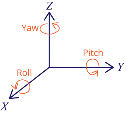
The MPU-6050 is a module with a 3-axis accelerometer and a 3-axis gyroscope. The gyroscope measures rotational velocity (rad/s). This is the change of the angular position over time along the X, Y, and Z-axis (roll, pitch, and yaw). This allows us to determine the orientation of an object. This helps us to measure acceleration, velocity, orientation, displacement and many other motion related parameter of a system or object. This module also has a (DMP) Digital Motion Processor inside it which is powerful enough to perform complex calculation and thus free up the work for Microcontroller.
The accelerometer measures acceleration (rate of change of the object’s velocity). It senses static forces like gravity (9.8m/s2) or dynamic forces like vibrations or movement. The MPU-6050 measures acceleration over the X, Y, and Z-axis. Ideally, in a static object, the acceleration over the Z-axis is equal to the gravitational force, and it should be zero on the X and Y-axis.
Using the accelerometer’s values, it is possible to calculate the roll and pitch angles using trigonometry. However, it is not possible to calculate the yaw.
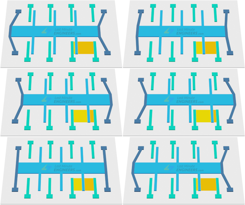
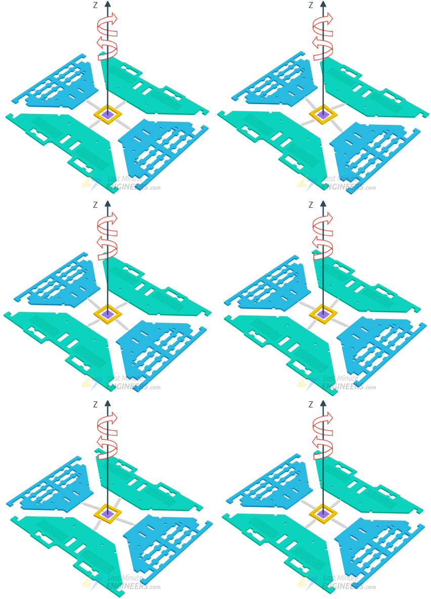
We can combine the information from both sensors to get more accurate information about the sensor orientation.
Apart from this we need to connect one green LED, One red LED and one Buzzer. The green MPU6050 Features
MEMS 3-aixs accelerometer and 3-axis gyroscope values combined
Power Supply: 3-5V
Communication: I2C protocol
Built-in 16-bit ADC provides high accuracy
Built-in DMP provides high computational power
Can be used to interface with other IIC devices like magnetometer
Configurable IIC Address
In-built Temperature sensor
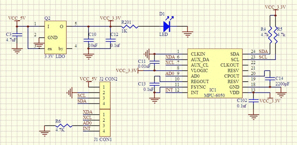
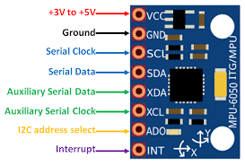
MPU6050 Pin out diagram: There is no need to connect Auxiliary pins anywhere. There is no need to connect interrupt pin to Arduino board. I2C address is also selected by the library automatically.
MPU-6050 Accelerometer and Gyroscope Sensor with Arduino:
The VCC & GND are connected to 5 volts DC and ground pins of Arduino. SCL (Serial clock) is clock input to the module which can be given from Pin A5 of Arduino. SDA (Serial Data) is connected to Pin A4 of Arduino. Green LED is connected to Arduino Pin 2 which will switch on as soon as Arduino is switched on. The Red LED and Buzzer are are connected to Pin 3 and Pin 4 of Arduino which will switch on as soon as we cross the set limits of any of the parameters.
MPU-6050 Accelerometer and Gyroscope Sensor with Node MCU:
The VCC & GND are connected to 3.3 volts DC and ground pins of Node MCU. SCL (Serial clock) is clock input to the module which can be given from Pin GPIO5 of Node MCU. SDA (Serial Data) is connected to Pin GPIO4 of Node MCU. Green LED is connected to Node MCU Pin GPIO2 which will switch on as soon as Node MCU is switched on. The Red LED and Buzzer are are connected to Pin GPIO3 and Pin GPIO4 of Node MCU which will switch on as soon as we cross the set limits of any of the parameters
MPU-6050 Accelerometer and Gyroscope Sensor with ESP32:
The VCC & GND are connected to 3.3 volts DC and ground pins of ESP32. SCL (Serial clock) is clock input to the module which can be given from Pin GPI22 of Node MCU. SDA (Serial Data) is connected to Pin GPI21 of ESP32. Green LED is connected to Node MCU Pin GPIO2 which will switch on as soon as ESP32 is switched on. The Red LED and Buzzer are are connected to Pin GPIO3 and Pin GPIO4 of ESP32 which will switch on as soon as we cross the set limits of any of the parameters
