801S Vibration Sensor interfacing
with Arduino, Node MCU, ESP32

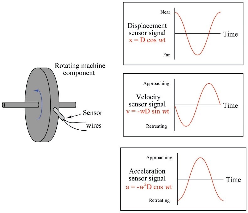
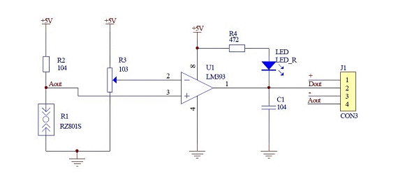
Whenever any machine is installed on the bed and coupled to any other machine or equipment there are varity of mis-alignments which cause vibration which can be detected by mounting different types of sensors at shaft, body, bed etc., This sensor 801S sensor is a simple Vibration sensor and it does not analyse or detect vibration Axis wise for which you need to select a different one. This sensor is general purpose Vibration sensor which has a popular comparator LM393 and whenver the value of vibration is more than the set value the comparator triggers a square value output using Schimitt trigger and Red LED will be lit and simultaneously buzzer starts making sound.
Vibration switch recognizes the amplitude of the vibration to which it is exposed. The switch response can be electrical contact closure or contact opening. The electrical contact may be either an electromechanical relay or a solid-state device.

Whenever any machine is installed on the bed and coupled to any other machine or equipment there are varity of mis-alignments which cause vibration which can be detected by mounting this sensor on the shaft or the body. It does not analyse or detect vibration Axis wise for which you need to select a different one. This sensor 801S is a general purpose Vibration sensor which has a popular comparator LM393 and whenver the value of vibration is more than the set value the comparator triggers a square value output using Schimitt trigger and Red LED will be lit and simultaneously buzzer starts making sound.

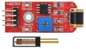
A vibration sensor is a piezoelectric sensor. It consists of a transducer that converts mechanical energy caused by vibration or change in motion to an electrical signal output by the principle of the piezoelectric effect. The sensor can monitor the changes in acceleration, pressure, temperature, and force and convert them into electrical output. But cannot make any distinction between different types elements. The 801S Vibration sensor is a micro shock-detecting sensor that works by changing its resistance when it detects any shock or vibration.

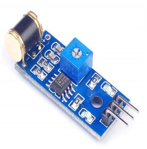
The 801S vibration sensor module includes two chips as its major component; 801S and an LM393 comparator. The module has a potentiometer to set a threshold value for the output signal or to adjust the sensitivity. The sensor has four pins of which two are power pins and the other two are for the output signal. The Analog output does not have much of relavance as we are interested only in the presence or absense of vibration.
801S Vibration Sensor interfacing with Arduino:
This Sensor has 4 pins VCC and GND of this sensor module is connected to 5 volts DC and ground pin of Arduino. D0 or Digital out is connected to Pin 7 of the Arduino. A0 or Analog out is connected to A0 Analog pin of Arduino. A0 has ADC (analog to Digital Conveter) which converts Analog output of 801S into equivalent digital output. There are two LEDs and one buzzer connected to the Arduino. The Green LED is connected to Pin 2 of Arduino to indicate the power on condtion. The Red LED is connected to Arduino Pin 3 and Buzzer to Pin 4 of the Arduino. Both of these turn on whenever the Pin 7 goes high which is set by us on the potentiometer connected to the comparator.
801S Vibration Sensor interfacing with Node MCU:
This Sensor has 4 pins VCC and GND of this sensor module is connected to 5 volts DC and ground pin of Node MCU. D0 or Digital out is connected to Pin GPIO7 of the Node MCU. A0 or Analog out is connected to A0 Analog pin of Node MCU. A0 has ADC (analog to Digital Conveter) which converts Analog output of 801S into equivalent digital output. There are two LEDs and one buzzer connected to the Node MCU. The Green LED is connected to Pin GPIO2 of Arduino to indicate the power on condtion. The Red LED is connected to Node MCU Pin GPIO3 and Buzzer to Pin 4 of the Node MCU. Both of these turn on whenever the Pin GPIO7 goes high which is set by us on the potentiometer connected to the comparator.
801S Vibration Sensor interfacing with ESP32:
This Sensor has 4 pins VCC and GND of this sensor module is connected to 5 volts DC and ground pin of ESP32. D0 or Digital out is connected to Pin GPIO7 of the ESP32. A0 or Analog out is connected to A0 Analog pin of ESP32. A0 has ADC (analog to Digital Conveter) which converts Analog output of 801S into equivalent digital output. There are two LEDs and one buzzer connected to the ESP32. The Green LED is connected to Pin GPIO2 of ESP32 to indicate the power on condtion. The Red LED is connected to Node MCU Pin GPIO3 and Buzzer to Pin 4 of the ESP32. Both of these turn on whenever the Pin GPIO7 goes high which is set by us on the potentiometer connected to the comparator.
