Ball Tilt sensor Interfaced
with Arduino, Node MCU, ESP32

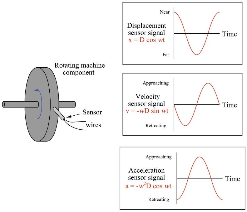
Whenever any machine is installed on the bed and coupled to any other machine or equipment there are varity of mis-alignments which cause vibration which can be detected by mounting different types of sensors at shaft, body, bed etc., This sensor Ball Tilt sensor is a simple tilt sensor and it does not analyse or detect vibration Axis wise for which you need to select a different one. This sensor is general purpose Vibration sensor which has a popular comparator LM393 and whenver the value of vibration is more than the set value the comparator triggers a square value output using Schimitt trigger and Red LED will be lit and simultaneously buzzer starts making sound.


Whenever any machine is installed on the bed and coupled to any other machine or equipment there are varity of mis-alignments which cause vibration which can be detected by mounting certain sensors on the shaft or the body. One such sensor is Ball Tilt sensor which activates an alarm if for some reasons the tilt angle of the machine or coupled equipment exceeds more than the tilting angle set.
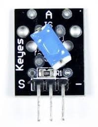
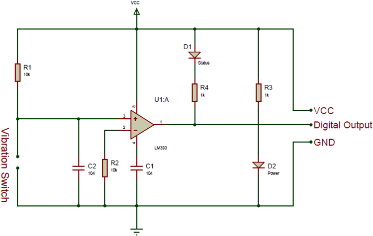
However, ball tile sensor does not analyse or detect vibration Axis wise for which you need to select a different one. This sensor is general purpose tilt sensor which has a popular comparator LM393 and whenver the value of tilt is more than the set value the comparator triggers a square value output using Schimitt trigger and Red LED will be lit and simultaneously buzzer starts making sound.
A ball tilt sensor is more of a switch that can detect basic motion, orientation or inclination. These switches are designed in such a way that a sufficient level of inclination makes or breaks the electrical connection. Such a signal can either be used as an indicator or can be used to turn something ON or OFF.
Although all tilt sensors work pretty much the same, their sizes and specifications may differ slightly.
They are small, cheap, easy to use and never wear out. Their simplicity makes them popular for use in toys, gadgets, robots, and other devices whose functioning depends on inclination.
While not as accurate or flexible as an accelerometer, the tilt sensor can detect motion or orientation quite well. Another advantage of using a tilt sensor is that it can be used as a standalone sensor. The accelerometer, on the other hand, outputs a digital or analog voltage that must be analyzed with additional circuitry.
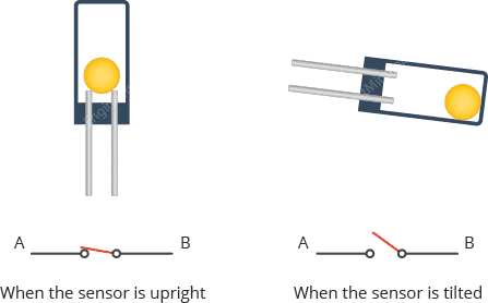
A ball tilt sensor is typically made up of a metal tube with a little metal ball that rolls around in it. One end of the cavity has two conductive elements (poles). The sensor is designed in such a way that a sufficient level of tilt allows the ball to roll, making or breaking an electrical connection.
When the sensor is upright the ball touches the poles and makes an electrical connection. And when the sensor is tilted the ball rolls off the poles and the connection is broken.
Ball Tilt sensor Interfaced with Arduino:
Tilt sensor has 3 pins of which 2 pins are connected to Arduino 5 volts DC pin and Ground. The 3rd Pin is Digital out or Signal Pin which needs to be connected to Pin 7 of Arduino. Apart from this there are two LEDs and one Buzzer connected to Arduino as indicators. Green LED is connected to Pin 2 of Arduino which will go High whenever Arduino is powered up indicating power up condition. Red LED and Buzzer are connected to Pin 3 and Pin 4 of Arduino. When the Pin 7 is triggered by Tilt sensor both Pin 3 and Pin 4 go high which turns on Red LED and Buzzer starts making sound.
Ball Tilt sensor Interfaced with Node MCU:
Tilt sensor has 3 pins of which 2 pins are connected to Node MCU 3.3 volts DC pin and Ground. The 3rd Pin is Digital out or Signal Pin which needs to be connected to Pin GPIO7 of Node MCU. Apart from this there are two LEDs and one Buzzer connected to Node MCU as indicators. Green LED is connected to Pin GPIO2 of Node MCU which will go High whenever Node MCU is powered up indicating power up condition. Red LED and Buzzer are connected to Pin GPIO3 and Pin GPIO4 of Node MCU. When the Pin GPIO7 is triggered by Tilt sensor both Pin GPIO3 and Pin GPIO4 go high which turns on Red LED and Buzzer starts making sound.
Ball Tilt sensor Interfaced with ESP32:
Tilt sensor has 3 pins of which 2 pins are connected to ESP32 3.3 volts DC pin and Ground. The 3rd Pin is Digital out or Signal Pin which needs to be connected to Pin GPIO7 of ESP32. Apart from this there are two LEDs and one Buzzer connected to ESP32 as indicators. Green LED is connected to Pin GPIO2 of ESP32 which will go High whenever ESP32 is powered up indicating power up condition. Red LED and Buzzer are connected to Pin GPIO3 and Pin GPIO4 of ESP32. When the Pin GPIO7 is triggered by Tilt sensor both Pin GPIO3 and Pin GPIO4 go high which turns on Red LED and Buzzer starts making sound.
