Rotary Encoder interfacing with Arduino, Node MCU, ESP32
with Seven Segment Display


Encoders are used to translate rotary or linear motion into a digital signal. Usually this is for the purpose of monitoring or controlling motion parameters such as speed, rate, direction, distance or position.
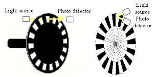
The Optical Encoders typically consist of a rotating and a stationary electronic circuit. The rotor is usually a metal, glass, or a plastic disc mounted on the encoder shaft. The disc has some kind of optical pattern, which is electronically decoded to generate position information. From one side of the disc the light source such as LED will put the light and through the pattern the light travels and hits photo transistors on the other side. We can use this for determining the speed of the rotor.

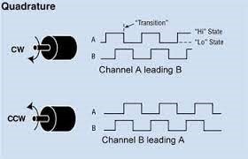
Encoder uses quadrature technology to determine direction of rotation: Inside a quadrature encoder, the code disk contains two tracks, usually denoted Channel A and Channel B. These tracks or channels are coded ninety electrical degrees out of phase, as indicated in the image, and this is the key design element that will provide the quadrature encoder its functionality. n applications requiring direction sensing, a controller can determine the direction of movement based on the phase relationship between Channels A and B.


As illustrated in the example optical encoder figure above, when the encoder is rotating in a clockwise direction, its signal will show Channel A leading Channel B, and the reverse will happen when the quadrature encoder rotates counterclockwise.
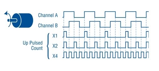
When more resolution is needed, it is possible for the counter to count the leading and trailing edges of the quadrature encoder’s pulse train from one channel, which doubles (x2) the number of pulses per revolution. Counting both the leading and trailing edges of both channels (A and B channels) of a quadrature encoder will quadruple (x4) the number of pulses per revolution. This technique is known as interpolation and will depend on how the signal is decoded through the users drive, PLC, or Controller.
As a result, 10,000 pulses per turn can be generated from a 2,500 PPR quadrature encoder. Typically with a Dynapar encoder, this 4x signal will be accurate to better than ±1 count. Likewise, 40,000 pulses can be generated from a 10,000 PPR quadrature encoder.
Rotary Encoder interfacing with Arduino:
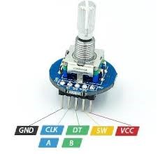
VCC and GND are connected to 5volts and ground of Arduino. The encoder also has a switch SW (active low) which can be connected to Pin 10 of Arduino. There are two outputs CLK and DT which may be connected to Pin 8 and Pin 9 of Arduino. There are two LEDs and one buzzer provided for any signalling to be high lighted to user. The green LED is connected to Arduino Pin 2 which indicates power on indication.
Rotary Encoder interfacing with Node MCU:
VCC and GND are connected to 3.3volts and ground of Node MCU. The encoder also has a switch SW (active low) which can be connected to Pin GPIO10 of Node MCU. There are two outputs CLK and DT which may be connected to Pin GPIO8 and Pin GPIO9 of Node MCU. There are two LEDs and one buzzer provided for any signalling to be high lighted to user. The green LED is connected to Node MCU Pin GPIO2 which indicates power on indication.
Rotary Encoder interfacing with ESP32:
VCC and GND are connected to 3.3volts and ground of ESP32. The encoder also has a switch SW (active low) which can be connected to Pin GPIO10 of ESP32. There are two outputs CLK and DT which may be connected to Pin GPIO8 and Pin GPIO9 of ESP32. There are two LEDs and one buzzer provided for any signalling to be high lighted to user. The green LED is connected to ESP32 Pin GPIO2 which indicates power on indication.
