Shock or Vibration Sensor SW-420 Interfacing
with Arduino, Node MCU and ESP32


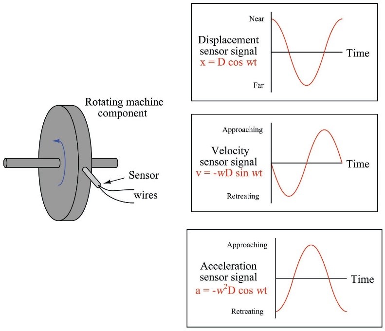
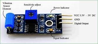
Whenever any machine is installed on the bed and coupled to any other machine or equipment there are varity of mis-alignments which cause vibration which can be detected by mounting different types of sensors at shaft, body, bed etc., This sensor SW-420 sensor is a simple tilt sensor and it does not analyse or detect vibration Axis wise for which you need to select a different one. This sensor is general purpose Vibration sensor which has a popular comparator LM393 and whenver the value of vibration is more than the set value the comparator triggers a square value output using Schimitt trigger and Red LED will be lit and simultaneously buzzer starts making sound.
Vibration switch recognizes the amplitude of the vibration to which it is exposed. The switch response can be electrical contact closure or contact opening. The electrical contact may be either an electromechanical relay or a solid-state device.
There is no analog value available as such so we do not need any LCD screen.
Shock or Vibration Sensor SW-420 Interfacing with Arduino:
There are only 3 Pins on the sensor of which VCC is connected to 5 volts Pin of Arduino and GND Pin of the sensor is connected to GND Pin of Arduino. Digital out is connected to one of the digital Pins say Pin7 of Arduino. We also have a green LED connected for power On indication which also needs to be connected to any digital Pin 2 using 220 ohms current limiting resistor. Same way Red LED is connected to one of the Digital Pin 3 and this is triggered whenever the threshold value exceeds the set value on the potentiometer (which is adjustable). This LED is also provided with 220 ohms current limiting resistor connected to ground. A buzzer is connected to one of the digital Pin 4 of Arduino having PWM output with current limited by 100 ohms resistor. Whenever The Digital output of the sensor module is triggered the buzzer will be switched On.

Shock or Vibration Sensor SW-420 Interfacing with Node MCU:
There are only 3 Pins on the sensor of which VCC is connected to 3.3 volts Pin of Node MCU and GND Pin of the sensor is connected to GND Pin of Node MCU. Digital out is connected to one of the digital Pins say Pin GPIO7 of Node MCU. We also have a green LED connected for power On indication which also needs to be connected to any digital Pin GPIO2 using 220 ohms current limiting resistor. Same way Red LED is connected to one of the Digital Pin GPIO3 and this is triggered whenever the threshold value exceeds the set value on the potentiometer (which is adjustable). This LED is also provided with 220 ohms current limiting resistor connected to ground. A buzzer is connected to one of the digital Pin GPIO4 of Node MCU having PWM output with current limited by 100 ohms resistor. Whenever The Digital output of the sensor module is triggered the buzzer will be switched On.

Shock or Vibration Sensor SW-420 Interfacing with ESP32:
There are only 3 Pins on the sensor of which VCC is connected to 3.3 volts Pin of ESP32 and GND Pin of the sensor is connected to GND Pin of ESP32. Digital out is connected to one of the digital Pins say Pin GPIO7 of ESP32. We also have a green LED connected for power On indication which also needs to be connected to any digital Pin GPIO2 using 220 ohms current limiting resistor. Same way Red LED is connected to one of the Digital Pin GPIO3 and this is triggered whenever the threshold value exceeds the set value on the potentiometer (which is adjustable). This LED is also provided with 220 ohms current limiting resistor connected to ground. A buzzer is connected to one of the digital Pin GPIO4 of ESP32 having PWM output with current limited by 100 ohms resistor. Whenever The Digital output of the sensor module is triggered the buzzer will be switched On.

