ADS1115 16-Bit ADC – 4 Channel interfacing
with Arduino, Node MCU, ESP32
Arduino boards come with a built-in 10-bit ADC that has a somewhat limited capability. The AD1115 has a 16-bit ADC resolution. This means the smallest voltage that Arduino can measure is 5V / 1024 = 0.0049V (or 4.9mV). Whereas the smallest voltage that ADS1115 can measure is 5V / 65536 = 0.000076V (76uV). Thus compared to Arduino ADC, the ADS1115 can measure a wide range of voltage.

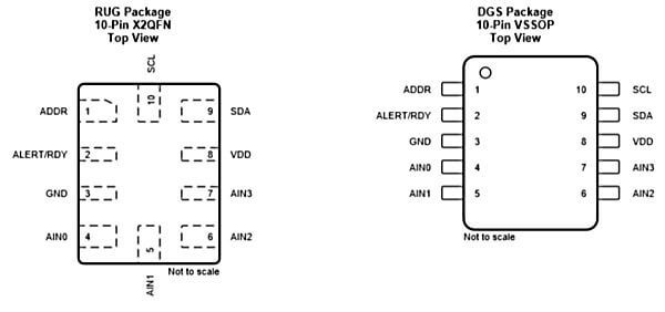
Pin 1 is the ADDR pin that selects the I2C address for the chip.
Pin 2 is the Alert/Ready pin which serves as a data ready and alert signal.
Pin 3 is the GND terminal.
Pins 4, 5, 6 & 7 are the four (4) ADC input pins. We can use these pins as either four (4) single-ended inputs or two (2) differential inputs.

Pin 8 is the positive power supply pin which accepts 2.0 V to 5.5 V
Pins 9 and 10 are the terminals for the I2C interface, SDA and SCL respectively.
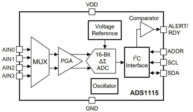
functional diagram for the ADS1115 Chip:
Initially a multiplexer selects the input signal. Then, the selected signal feeds into a Programmable Gain amplifier (PGA). The PGA can programmed to provide amplification of small signals prior to conversion.

Subsequently, the input is converted by a 16-bit Delta Sigma converter. The converter uses its own built-in voltage reference and built-in oscillator in measuring the input signal. Finally, the result of the conversion goes into the I2C interface. Also, a comparator provides a signal to the external interface that the result is ready for fetching.
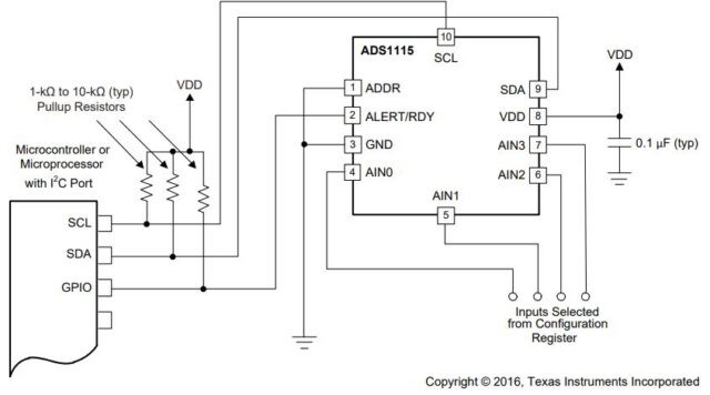
Typical Connections of the ADS1115
The principle I2C connections for the ADS1115 is shown in the image below.
The ADS1115 interfaces directly to standard mode, fast mode, and high-speed mode I2C controllers. Any microcontroller I2C peripheral, including master-only and single-master I2C peripherals, operates with the ADS1115.

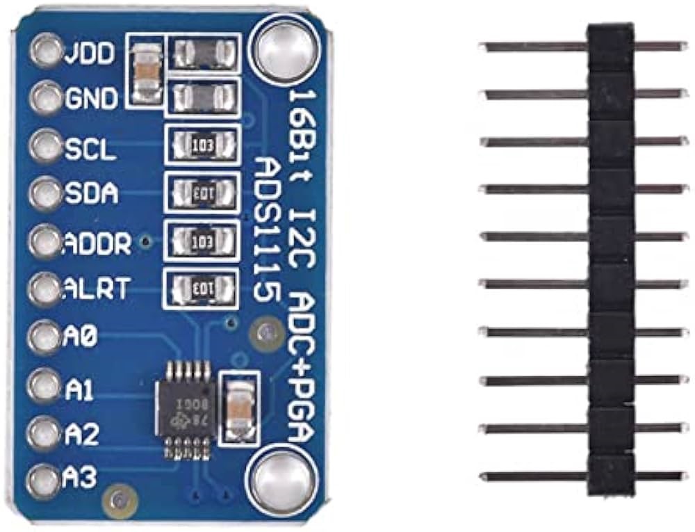
ADS1115 is an ultra-small, low-power, 16-bit precision AD converter (Analog to Digital Converter) with an internal reference voltage. Mainly used in high-precision instrumentation, automotive electronics, battery voltage collection and other high-precision collection occasions. Its general function is to amplify, improve accuracy, and convert Analog to digital for data analysis.
ADS1115 has an onboard reference and oscillator. Data is transmitted through an I2C compatible serial interface; 4 I2C slave addresses can be selected. ADS1115 uses a single working power supply ranging from 2.0V to 5.5V.
The ADS1115 can perform conversion operations at a rate of up to 860 samples per second (SPS). The ADS1115 has an onboard programmable gain amplifier (PGA) that can provide an input range as low as ±256mV from the power supply voltage, thus enabling the measurement of large and small signals with high resolution. In addition, the ADS1115 also has an input multiplexer (MUX), which can provide 2 differential inputs or 4 single-ended inputs.
ADS1115 can work in continuous conversion mode or single trigger mode, the latter will automatically power off after a conversion is completed, thereby greatly reducing the current consumption in the idle state. ADS1115 has a specified temperature range from -40°C to +125°C.
ADS1115 16-Bit ADC – 4 Channel interfacing with Arduino:
VDD & GND pins of ADS1115 are connected to 5 volts DC and ground pins of Arduino. SCL (clock) is connected to SCL of Arduino and SDA (Data) is connected to Data of Arduino. A0, A1, A2 and A3 are 4 numbers of 16-bit precision A to D converter to which we can connect analog inputs. In this case we have connected a poteniometer to A0 input and the digital output will be presented to Arduino through I2C interface and will be displayed on LCD display which is also connected to Arduino using I2C interface.
ADS1115 16-Bit ADC – 4 Channel interfacing with Node MCU:
VDD & GND pins of ADS1115 are connected to 3.3 volts DC and ground pins of Node MCU. SCL (clock) is connected to SCL Pin GPIO5 of Node MCU and SDA (Data) is connected to Pin GPIO4 of Node MCU. A0, A1, A2 and A3 are 4 numbers of 16-bit precision A to D converter to which we can connect analog inputs. In this case we have connected a poteniometer to A0 input and the digital output will be presented to Node MCU through I2C interface and will be displayed on LCD display which is also connected to Node MCU using I2C interface.
ADS1115 16-Bit ADC – 4 Channel interfacing with ESP32:
VDD & GND pins of ADS1115 are connected to 3.3volts DC and ground pins of ESP32. SCL (clock) is connected to SCL Pin GPIO22 of ESP32 and SDA (Data) is connected to Pin GPIO21 of ESP32. A0, A1, A2 and A3 are 4 numbers of 16-bit precision A to D converter to which we can connect analog inputs. In this case we have connected a poteniometer to A0 input and the digital output will be presented to ESP32 through I2C interface and will be displayed on LCD display which is also connected to ESP32 using I2C interface.
