MQ-2 Flammable Gas and Smoke Sensor interfacing
with Arduino, Node MCU, ESP32 with LCD display


The MQ-2 sensor is used to detect hazardous or flammable gas or smoke but it needs a heating element in order to properly detect combustible gasses but, a heating element close to combustible gasses could be disastrous, so the sensor is manufactured with an anti-explosion network made out of two thin layers of stainless steel mesh as you can see in the image below. The heating element is placed inside this stainless steel mesh.
This mesh structure also provides resistance against dust and other suspended particulars and it only lets in the gaseous elements from the atmosphere. If we decap the sensor we can see the sensor is made out of two major elements. First one is the heating element which is made out of nichrome wire and other is the sensing element that is made out of a platinum wire with a coating of tin dioxide.
MQ-2 is a smoke and combustible gas sensor from Winsen. It can detect flammable gas in a range of 300 – 10000ppm. It’s most common use is domestic gas leakage alarms and detectors with a high sensitivity to propane and smoke.
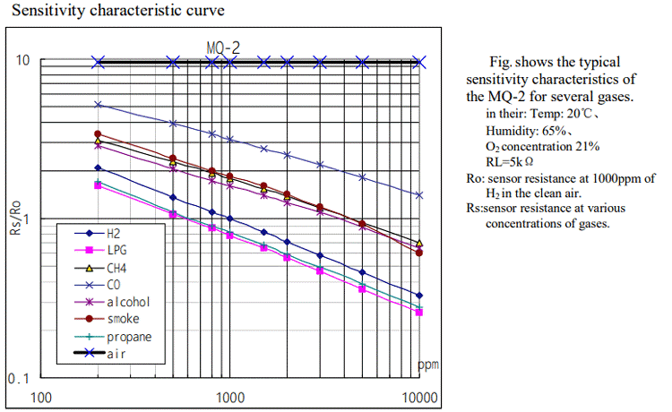
In the logarithmic graph, RS is the sensing resistance during the presence of a particular gas. While R0 is the sense resistance in clean air. This sensor is designed to detect smoke so this sensor resistance will change depending on the concentration of smoke present in the atmosphere.
In the logarithmic graph, RS is the sensing resistance during the presence of a particular gas. While R0 is the sense resistance in clean air. This sensor is designed to detect smoke so this sensor resistance will change depending on the concentration of smoke present in the atmosphere.
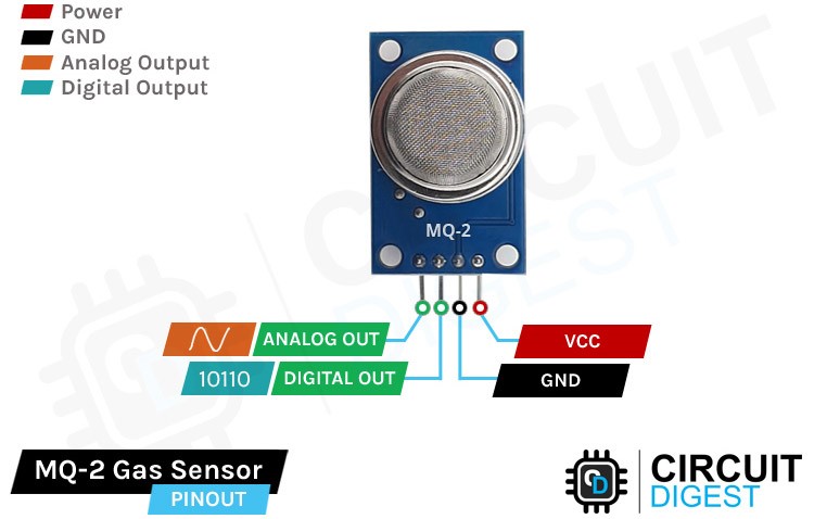
MQ-2 Gas Sensor Pinout
The MQ-2 Gas detection sensor module has four pins VCC, GND, Aout, and Dout that can be used to get the needful information out of the sensor, The pinout of the MQ-2 Gas detection sensor is given below:

VCC is the power supply pin of the Gas Detection Sensor that can be connected to 5V of the supply.
GND is the ground pin of the board and it should be connected to the ground pin of the Arduino.
DOUT is the Digital output pin of the board, output low indicates gas or smoke is not present in the atmosphere and output high indicates gas or smoke is present in the atmosphere.
AOUT is the Analog output pin of the board that will give us an analog signal which will vary between vcc and ground based on the gas level detected
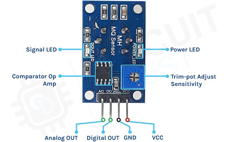
MQ-2 Gas and Smoke Sensor Module – Parts

Like all the other basic sensor modules, this MQ-2 Gas and smoke sensor module has four pins, two of which are for VCC and Gnd and the other two can simultaneously output analog and digital data. To power the circuit we are using the 5V pin of the arduino because the operating voltage range of this module is 5V with ±0.1% tolerance. As you can see in the image above the module has two onboard LEDs. The power LED turns on when power is applied to the board and the Dout LED turns on when the trigger value set by the potentiometer is reached. This board also has a comparator OP-Amp onboard that is responsible for converting the incoming analog signal from the gas sensor to a digital signal. We also have a sensitivity adjustment Trim-pot, with that we can adjust the sensitivity of the device. Finally we have some resistor capacitors for decoupling and filtering.

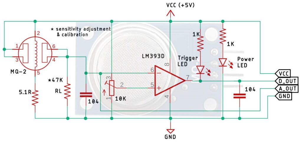
In the schematic, we have a LM393 op-amp which is a low-power low offset voltage op-amp that can be powered from a +5V supply. But powering the circuit with 3.3V is not an option because the minimum operating voltage of this MQ-2 sensor is 5V. The main job of this op- amp is to convert the incoming analog signal to digital signal. Other than that we also have an onboard 10K potentiometer that is used to adjust the sensitivity of the MQ-2 Gas Sensor module or the triggering voltage of the module.Other than that we have two LEDs. The first one is a power LED and the other one is the trigger LED. The power LED turns on when power is applied to the board and the trigger LED turns on when a certain set threshold is reached. Finally we have two decoupling capacitors that are used to reduce noise in the board.
MQ-2 Combustible Gas Sensor with Arduino UNO – Connection Diagram
Now that we have complete understanding of how the MQ-2 gas sensor works we can connect all the required wires to Arduino uno. This section of the article will be divided into two parts, one shows analog output and another one shows the digital output. Let’s begin with analog circuitry
MQ-2 Flammable Gas and Smoke Sensor interfacing with Arduino:
VCC & GND Pin of sensor is connected to 5 volts DC and ground of Arduino. Analog output A0 is connected to Pin A0 of ADC (Analog to Digital Converter). Digital Out is connected to Pin 7 of Arduino which when triggered should Pull up Pin 9 for further connections. Then we have two LEDs and one Buzzer to be connected to Green to Pin 2, Red to Pin 3 and Buzzer to Pin 4. Green will light to indicate that the Arduino is on. Red LED and Buzzer should turn on when smoke is detected and Pin 7 goes high. Pin 9 shall be connected to Hooter, door opening mechanism for evacuation.
MQ-2 Flammable Gas and Smoke Sensor interfacing with Node MCU:
VCC & GND Pin of sensor is connected to 3.3 volts DC and ground of Node MCU. Analog output A0 is connected to Pin ADC0 (Analog to Digital Converter). Digital Out is connected to Pin GPIO7 of Node MCU which when triggered should Pull up Pin GPIO9 for further connections. Then we have two LEDs and one Buzzer to be connected to Green to Pin GPIO2, Red to Pin GPIO3 and Buzzer to Pin GPIO4. Green will light to indicate that the Node MCU is on. Red LED and Buzzer should turn on when smoke is detected and Pin GPIO7 goes high. Pin GPIO9 shall be connected to Hooter, door opening mechanism for evacuation.
MQ-2 Flammable Gas and Smoke Sensor interfacing with ESP32 :
VCC & GND Pin of sensor is connected to 3.3 volts DC and ground of ESP32. Analog output A0 is connected to Pin ADC0 (Analog to Digital Converter). Digital Out is connected to Pin GPIO7 of ESP32 which when triggered should Pull up Pin GPIO9 for further connections. Then we have two LEDs and one Buzzer to be connected to Green to Pin GPIO2, Red to Pin GPIO3 and Buzzer to Pin GPIO4. Green will light to indicate that the ESP32 is on. Red LED and Buzzer should turn on when smoke is detected and Pin GPIO7 goes high. Pin GPIO9 shall be connected to Hooter, door opening mechanism for evacuation.
