Flame sensor interfacing with Arduino
Node MCU, ESP32 with LED and Buzzer

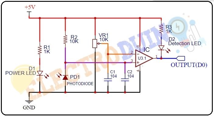
How IR Infrared Flame Sensor Module Works: At first, we need to connect the Sensor to the 5v power supply. Then set the threshold voltage at the Non-Inverting input (3) of the IC according to the absence of flame/fire by rotating the preset knob for setting the sensor sensitivity.
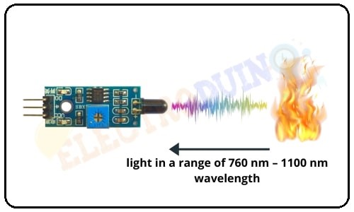
When this sensor detects fire/flame (light in a range of 760 nm – 1100 nm wavelength) then the resistance of the Phototransistor decreases. Then the maximum amount of voltage will be allocated across the Resistor(R2). So, a Low amount of voltage from the Phototransistor is given to the Inverting input (2) of the IC. Then the Comparator IC compares this voltage with the threshold voltage. In this condition, this input voltage is less than the threshold voltage, so the sensor output goes LOW (0).

In contrast, when the Flame Sensor module does not detect fire/flame (light in a range of 760 nm – 1100 nm wavelength) then the resistance of the Phototransistor is High. Then the maximum amount of voltage will be allocated across the Phototransistor. So, a High amount of voltage from the Phototransistor is given to the Inverting input (2) of the IC. Then the Comparator IC compares this voltage with the threshold voltage. In this condition, this input voltage is greater than the threshold voltage, so the sensor output goes High (1).
A flame detector is a sensor outlined to identify and answer to the presence of a flame or fire. Responses to a recognized flame depend on the installation but can combine sounding an alarm, deactivating a fuel line and activating a fire suppression system.
In this project, we are using an IR based flame sensor. It can identify infrared light with a wavelength ranging from 700nm to 1000nm and its exposure angle is about 60°.
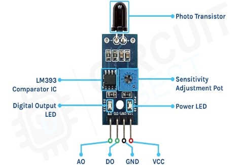
A flame sensor module includes a photodiode (IR receiver), resistor, capacitor, potentiometer and LM393 comparator in an integrated circuit.

Working of Flame Sensor with Arduino
Arduino Uno is an open-source microcontroller board that depends on an ATmega328p microcontroller. The flame sensor recognizes the presence of fire or flame based on the Infrared (IR) wavelength released by the flame. It gives logic 1 as output if the flame is identified, otherwise, it gives logic 0 as output. Arduino Uno controls the logic level on the output pin of the sensor and offers additional tasks such as activating the buzzer and LED, sending an alert notification.
Pin configuration and Module Parts
The flame sensor module has only very few components, which include an IR photodiode, an LM393 comparator IC, and some complimentary passive components. The power LED will light up when the module is powered and the D0 LED will turn off, when a flame is detected.
The sensitivity can be adjusted with the trimmer resistor onboard.
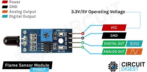
Flame Sensor Pin Out:
The Flame Sensor module has a total of 4 pins.


Flame sensor interfacing with Arduino:
VCC & GND of this flame sensor are connected to 5 volts DC and ground Pin of Arduino. Digital Out of the sensor is connected to Pin 7 of Arduino which will trigger Pin 9 for further action. Analog Out connected to one of the Analog pins A0 to A5 of Arduino say A0 Pin. There is no Analog value as such to be read as any flame big or small requires attention which will be taken care by Pin 9. Then we have two LEDs and a Buzzer connected to Pin 2, Pin 3, Pin 4. The green LED connected to Pin 2 would light when the Arduino is switched on. Pin 3 connected to Red LED and Buzzer connected to Pin 4 will light whenever Pin 9 goes high.
Flame sensor interfacing with Node MCU:
VCC & GND of this flame sensor are connected to 3.3 volts DC and ground Pin of Node MCU. Digital Out of the sensor is connected to Pin GPIO7 of Node MCU which will trigger Pin GPIO9 for further action. Analog Out connected to Analog pin ADC0 Node MCU. There is no Analog value as such to be read as any flame big or small requires attention which will be taken care by Pin GPIO9. Then we have two LEDs and a Buzzer connected to Pin GPIO2, Pin GPIO3, Pin GPIO4. The green LED connected to Pin GPIO2 would light when the Node MCU is switched on. Pin GPIO3 connected to Red LED and Buzzer connected to Pin GPIO4 will light whenever Pin 9 goes high.
Flame sensor interfacing with ESP32 :
VCC & GND of this flame sensor are connected to 3.3 volts DC and ground Pin of ESP32. Digital Out of the sensor is connected to Pin GPIO7 of ESP32 which will trigger Pin GPIO9 for further action. Analog Out connected to Analog pin ADC0 ESP32. There is no Analog value as such to be read as any flame big or small requires attention which will be taken care by Pin GPIO9. Then we have two LEDs and a Buzzer connected to Pin GPIO2, Pin GPIO3, Pin GPIO4. The green LED connected to Pin GPIO2 would light when the ESP32 is switched on. Pin GPIO3 connected to Red LED and Buzzer connected to Pin GPIO4 will light whenever Pin 9 goes high.
