MAX7219 LED Dot Matrix Display Interfacing
with Arduino, Node MCU, ESP32
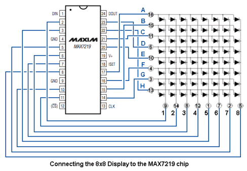
MAX7219 IC is capable of driving 64 individual LEDs while using only 3 wires for communication with the Arduino, and what’s more we can daisy chain multiple drivers and matrixes and still use the same 3 wires.
Pin 2, 3, 5,6,7,8, 10, and 11 are 0 to 7 digits.
14 to 17 & 20, 21 & 23 are segments of digits like SEG_A to SEG_G,
Pin22 is segment pin for a decimal point like SEG DP
The 64 LEDs are driven by 16 output pins of the IC. The question now is how is that possible. well the maximum number of LEDs light up at the same time is actually eight. The LEDs are arranged as 8×8 set of rows and columns. So the MAX7219 activates each column for a very short period of time and at the same time it also drives each row. So by rapidly switching through the columns and rows the human eye will only notice a continuous light.
The Dot Matrix Display
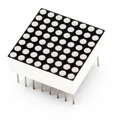
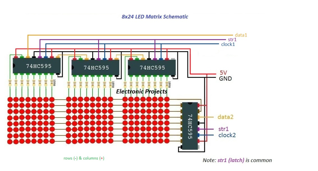
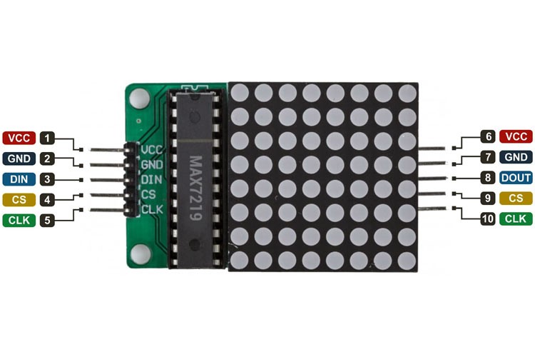
When we are talking about the MAX7219-based dot matrix display module, it consists of 64 LEDs connected in a row-column format so that we could easily control them with the multiplexing technique. That is why a typical single color 8×8 dot matrix unit has 16 pins, 8 for each row and 8 for each column.
The most common problem with multiplexing is that your microcontroller will always be busy refreshing the display and will not have the time to do other tasks. But with the help of MAX7219, you don’t need to worry about refreshing the display because this IC also takes care of that part. You just need to send serial data through SPI and it will automatically take care of the rest.
The MAX7219 can fully control 64 individual LEDs and it can simultaneously update the display with 800 Hz refresh rate, other than that if you need to control the brightness of the LEDs it has the option to do so with hardware and software. And it can do it simultaneously without interrupting the microcontroller.
MAX7219 LED Dot Matrix Display Interfacing with Arduino:
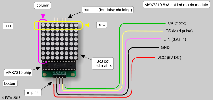
VCC and GND pins are connected to 5 volts DC and ground pins of Arduino. DIN (data input) pin used to send data to the module is connected to Pin 11 of Arduino, CS (chip select) pin used to enable or disable the module also called as LOAD is connected to Pin 10 of the Arduino.CLK (clock input) pin used to synchronize the data transfer is connected to digital output pin 13 of the Arduino.
MAX7219 LED Dot Matrix Display Interfacing with Node MCU:
VCC and GND pins are connected to 3.3 volts DC and ground pins of Node MCU. DIN (data input) pin used to send data to the module is connected to Pin GPIO4 of Node MCU, CS (chip select) pin used to enable or disable the module also called as LOAD is connected to Pin GPIO15 of the Node MCU.CLK (clock input) pin used to synchronize the data transfer is connected to digital output pin GPIO5 of the Node MCU.
MAX7219 LED Dot Matrix Display Interfacing with ESP32:
VCC and GND pins are connected to 3.3 volts DC and ground pins of ESP32. DIN (data input) pin used to send data to the module is connected to Pin GPIO21 of ESP32, CS (chip select) pin used to enable or disable the module also called as LOAD is connected to Pin GPIO5 of the ESP32. CLK (clock input) pin used to synchronize the data transfer is connected to digital output pin GPIO22 of the ESP32.
