Motion Detection Passive Infrared PIR HC-SR501 Sensor interfacing
with Arduino, Node MCU, ESP32

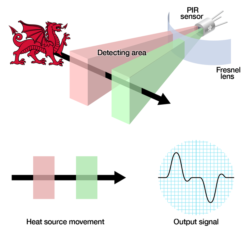
The passive infrared (PIR) sensor itself has two slots in it, each slot is made of a special material that is sensitive to IR. The lens used here is not really doing much and so we see that the two slots can ‘see’ out past some distance (basically the sensitivity of the sensor). When the sensor is idle, both slots detect the same amount of IR, the ambient amount radiated from the room or walls or outdoors. When a warm body like a human or animal passes by, it first intercepts one half of the PIR sensor, which causes a positive differential change between the two halves. When the warm body leaves the sensing area, the reverse happens, whereby the sensor generates a negative differential change. These change pulses are what is detected.

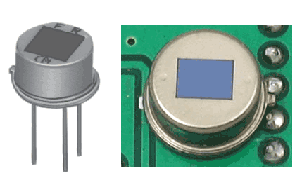
The PIR Sensor: The IR sensor itself is housed in a hermetically sealed metal can to improve noise/temperature/humidity immunity. There is a window made of IR-transmissive material (typically coated silicon since that is very easy to come by) that protects the sensing element. Behind the window are the two balanced sensors.
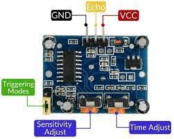
Motion detector has two potentiometers, one jumper and 3 pins for Arduino connectivity. Sensitivity adjust pot meter is used for adjusting the sensitivity of detection of object. If it is set to high then there could too many false triggers and if it is set too low some of the object may get undetected. If we are using the sensor for automatic lighting, false triggers are acceptable rather than not triggering when required.
Time adjust pot meter is used to adjust the time duration to which the echo pin must remain high. Like if we set it for 300 seconds then echo pin will remain high for 300 seconds or 5 minutes. That means if we use this for lighting the light once switches on will remain lit for 5 minutes.

Triggering mode slide switch can be set for single or multiple. Single means when a person is in the range the PIR will trigger once and will remain high for the time set. It will not trigger once again even if the person is around. On the other hand multiple or H means as long as the person is around the signal will remain high and go off only after set time after the person leaves the scene.
Output: Digital pulse high (3V) when triggered (motion detected) digital low when idle (no motion detected). Pulse lengths are determined by resistors and capacitors on the PCB and differ from sensor to sensor.
Sensitivity range : up to 20 feet (6 meters) 110° x 70° detection range
Motion Detection Passive Infrared PIR HC-SR501 Sensor interfacing with Arduino:
There are 3 pins provided on the sensor of which VCC and GND are connected to 5 volts DC and ground of Arduino. Echo Pin is connected to Pin 7 of Arduino which in turn triggers Pin 9 which could be used for activation of activity downstream. Then there are two LEDs and a buzzer connected of which Green LED would light up as soon as Arduino is powered up. Red LED and Buzzer are connected to Pin 3 and Pin 4 of Arduino. Both will turn on whenever the Pin 7 goes high indicating there is motion detected and someone is within the range of sensor.
Motion Detection Passive Infrared PIR HC-SR501 Sensor interfacing with Node MCU:
There are 3 pins provided on the sensor of which VCC and GND are connected to 3.3 volts DC and ground of Node MCU. Echo Pin is connected to Pin GPIO7 of Node MCU which in turn triggers Pin GPIO9 which could be used for activation of activity downstream. Then there are two LEDs and a buzzer connected of which Green LED would light up as soon as Node MCU is powered up. Red LED and Buzzer are connected to Pin GPIO3 and Pin GPIO4 of Node MCU. Both will turn on whenever the Pin GPIO7 goes high indicating there is motion detected and someone is within the range of sensor.
Motion Detection Passive Infrared PIR HC-SR501 Sensor interfacing with ESP32:
There are 3 pins provided on the sensor of which VCC and GND are connected to 3.3 volts DC and ground of ESP32. Echo Pin is connected to Pin GPIO7 of ESP32 which in turn triggers Pin GPIO9 which could be used for activation of activity downstream. Then there are two LEDs and a buzzer connected of which Green LED would light up as soon as ESP32 is powered up. Red LED and Buzzer are connected to Pin GPIO3 and Pin GPIO4 of ESP32. Both will turn on whenever the Pin GPIO7 goes high indicating there is motion detected and someone is within the range of sensor.
