Modulated InfraRed Proximity sensor interfaced
with Arduino, Node MCU, ESP32

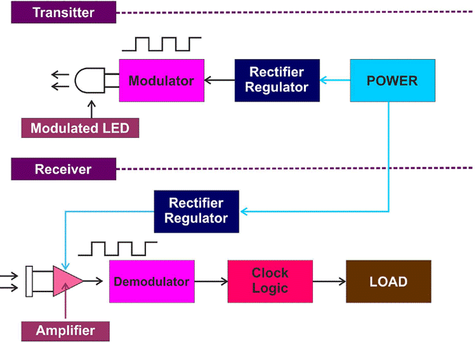
Normal sunlight has InfraRed Radiation as part of the spectrum of light waves transmitted by Sun. Hence if we use normal IR sensor it may sometimes not work properly. Hence, we modulate the IR radiation such that these sensors could be used in the normal day light as well.

E18-D80NK is a variable range non-contact detection sensor. It comes with a transmitter and receiver in a single module setup. The transmitter emits a modulated IR signal which is reflected by the object in its field of view or the path and the reflected signal is then collected by the receiver, providing a digital output to the microcontroller Arduino. Inside the IR sensor there is an IR diode which transmits IR rays which will be reflected by the object and reflected wave will be received by Photo transistor which triggers electronic circuit such Schmitt trigger which gives a pure square wave recognisable by Arduino.

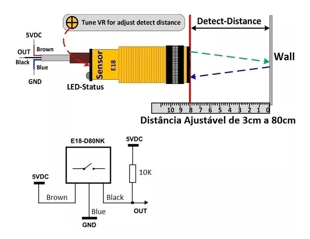
On the rear side of the IR sensor there is an indication LED which glows whenever the sensor detects an object. There is also Range adjustment Screw which can be turned clockwise or anti-clockwise such that at desired distance when the object is placed the IR sensor would trigger. IR proximity sensors are available in different ranges.


There are different models offering different ranges.
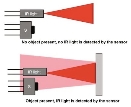
When there is no object there is no reflection so no IR light is received by photo transistor and hence there is no output. When there is an object in the way of IR rays, the IR rays are reflected and received by receiver. From Time-of-flight that is time taken by IR ray to reach the object and return back we can calculate the distance of the object because we know the speed of light.
Modulated InfraRed Proximity sensor interfaced with Arduino
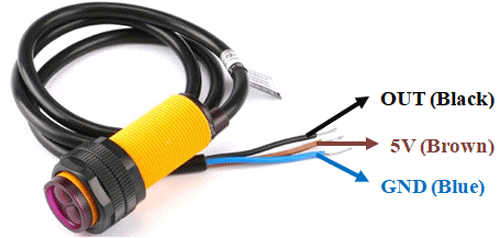
The IR sensor has 3 terminals of which 5 volts (Brown) and GND (Blue) are connected to 5 volts DC and GND or ground terminal of Arduino. The signal out which is a digital pulse is connected to Pin 7 of Arduino. In any case we have provided two LEDs and a Buzzer which are connected to provide certain information. The green LED is connected to Pin 2 which indicates power on condition. The Red LED and buzzer are connected to Pin 3 and Pin 4 of Arduino. This would light and buzzer will sound whenever the sensor encounters obstacle. When this Pin 7 is triggered, Arduino will compute the distance and display the same on LCD display or OLED.
Modulated InfraRed Proximity sensor interfaced with Node MCU
The IR sensor has 3 terminals of which 5 volts (Brown) and GND (Blue) are connected to 5 volts DC and GND or ground terminal of an external supply if 3.3 volts delivered by Node MCU does not give required performance. The signal out which is a digital pulse is connected to Pin GPIO7 of Node MCU. In any case we have provided two LEDs and a Buzzer which are connected to provide certain information. The green LED is connected to Pin GPIO2 which indicates power on condition. The Red LED and buzzer are connected to Pin GPIO3 and Pin GPIO4 of Node MCU. This would light and buzzer will sound whenever the sensor encounters obstacle. When this Pin 7 is triggered, Node MCU will compute the distance and display the same on LCD display or OLED.
Modulated InfraRed Proximity sensor interfaced with ESP32
The IR sensor has 3 terminals of which 5 volts (Brown) and GND (Blue) are connected to 5 volts DC and GND or ground terminal of an external supply if 3.3 volts delivered by Node MCU does not give required performance. The signal out which is a digital pulse is connected to Pin GPIO7 of ESP32. In any case we have provided two LEDs and a Buzzer which are connected to provide certain information. The green LED is connected to Pin GPIO2 which indicates power on condition. The Red LED and buzzer are connected to Pin GPIO3 and Pin GPIO4 of Node MCU. This would light and buzzer will sound whenever the sensor encounters obstacle. When this Pin 7 is triggered, Node MCU will compute the distance and display the same on LCD display or OLED.
