Temperature and Humidity sensor DHT22 interfacing
with Arduino, Node MCU and ESP32
The DHT22 has a temperature measuring range is from -40 to +125 degrees Celsius with +-0.5 degrees accuracy and humidity measuring range from 0 to 100% with 2.5% accuracy.
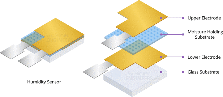
The humidity sensing component has two electrodes with a moisture-holding substrate (usually a salt or conductive plastic polymer) in between. As the humidity rises, the substrate absorbs water vapor, resulting in the release of ions and a decrease in the resistance between the two electrodes. This change in resistance is proportional to the humidity, which can be measured to estimate relative humidity. This change in resistance is measured with the onboard MCU’s ADC and the relative humidity is calculated. Since this MCU or SoC (System on Chip) does most of the job and provides the data to Arduino on request we can handle the rest of it easily.
Each DHT22 element is strictly calibrated in the laboratory which is extremely accurate in humidity calculation. The calibration coefficients are stored as programs in the OTP memory, which are used by the sensor’s internal signal detecting process.
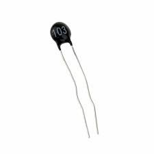
Thermistors are generally produced using powdered metal oxides or semiconductor made of ceramic materials and in both cases their resistance changes dramatically with temperature (by 100 ohms or more per degree).
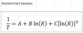
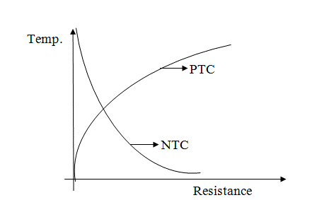
The term “NTC” stands for “Negative Temperature Coefficient,” which means that resistance decreases as temperature rises. Same way we also have PTC thermistors where the thermistors resistance increases as the temperature increases. However, in both the cases the characteristics are non linear as you can see in the picture above. We can use The Steinhart–Hart equation is a model of the resistance of a semiconductor at different temperatures where A, B and C are constants.
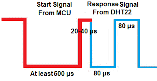
A single bus communication protocol is used to communicate between DHT22 and Arduino microcontroller. Before anything else happens Arduino will send start signal which will be responded by DHT22 as shown. This is followed by data consisting of decimal and integer parts. The total data is 40 bit long and its is MSB format. The Data format is as follows: 8bit integral RH data + 8bit decimal RH data + 8bit integral T data + 8bit decimal T data + 8bit checksum. If the data transmission is right, the check-sum should be the last 8bit of “8bit integral RH data + 8bit decimal RH data + 8bit integral T data + 8bit decimal T data”. Once the data transmission is completed the Arduino pin to which DHT22 is conncted will be pulled up again.
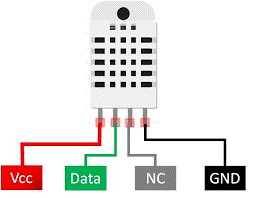
Temperature and Humidity sensor DHT22 Interfacing with Arduino: DHT22 has 4 pins of which VCC Pin is connected to 5 volts supply of Arduino. GND or Ground Pin is connected to Ground Pin of Arduino, Pin marked NC is not connected. Pin marked Dout or Serial Data is connected to any digital Pin of Arduino say Pin7.
For Power On indication Green LED is connected to Pin 2 of Arduino and Red LED is connected to Pin 3 of Arduino. Current limiting reistors of 220 ohms of both LEDs are tied together to the Arduino Ground circuit. Buzzer is connected to Pin 4 of Arduino. In case the temperature or Humidity is more than the set value then an alarm could be set which trigger Red LED and Buzzer.
Temperature and Humidity sensor DHT22 Interfacing with Node MCU: DHT22 has 4 pins of which VCC Pin is connected to 3.3 volts supply of Node MCU. GND or Ground Pin is connected to Ground Pin of Node MCU, Pin marked NC is not connected. Pin marked Dout or Serial Data is connected to any digital Pin of Node MCU say Pin GPIO7.
For Power On indication Green LED is connected to Pin GPIO2 of Node MCU and Red LED is connected to Pin GPIO3 of Node MCU. Current limiting reistors of 220 ohms of both LEDs are tied together to the Arduino Ground circuit. Buzzer is connected to Pin GPIO4 of Node MCU. In case the temperature or Humidity is more than the set value then an alarm could be set which trigger Red LED and Buzzer.
Temperature and Humidity sensor DHT22 Interfacing with ESP32: DHT22 has 4 pins of which VCC Pin is connected to 3.3 volts supply of ESP32. GND or Ground Pin is connected to Ground Pin of ESP32, Pin marked NC is not connected. Pin marked Dout or Serial Data is connected to any digital Pin of ESP32 say Pin GPIO7.
For Power On indication Green LED is connected to Pin GPIO2 of ESP32 and Red LED is connected to Pin GPIO3 of ESP32. Current limiting reistors of 220 ohms of both LEDs are tied together to the ESP32 Ground circuit. Buzzer is connected to Pin GPIO4 of ESP32. In case the temperature or Humidity is more than the set value then an alarm could be set which trigger Red LED and Buzzer.
