NTC and PTC Thermistors interfacing
with Arduino, Node MCU, ESP32 and display on LCD

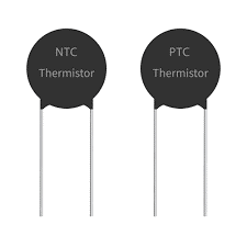
Thermistors are temperature sensitive semiconductors that exhibit a large change in resistance over a relatively small range of temperature. There are two main types of thermistors, positive temperature coefficient (PTC) and negative temperature coefficient (NTC). NTC thermistors exhibit the characteristic of resistance falling with increasing temperature. These are most commonly used for temperature measurement.


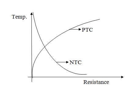
Thermistors are generally produced using powdered metal oxides or semiconductor made of ceramic materials and in both cases their resistance changes dramatically with temperature (by 100 ohms or more per degree). The term “NTC” stands for “Negative Temperature Coefficient,” which means that resistance decreases as temperature rises. Same way we also have PTC thermistors where the thermistors resistance increases as the temperature increases. However, in both the cases the characteristics are non linear as you can see in the picture above.
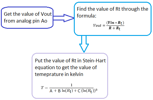
We can use The Steinhart–Hart equation is a model of the resistance of a semiconductor at different temperatures where A, B and C are constants.
The graphical representation of Temperature verses Resistance for both NTC and PTC type of Thermistors is drawn here below. You would notice that both PTC and NTC characteristics are non-linear. Hence we need to use Steinhart–Hart equation to apply corrections.

thematically the thermistor resistance can only be computed with the help of the Stein-Hart equation.
T = 1 / (A + Bln(Rt) + Cln (Rt)3 )
Where, A, B and C are the constants, Rt is the thermistor resistance and ln represent log.
The constant value for the thermistor used in the project is A = 1.009249522×10⁻³,
B=2.378405444×10⁻⁴,
C= 2.019202697×10⁻⁷. These constant values can be obtained from the calculator here by entering the three resistance values of thermistor at three different temperatures.

You can either get these values of constant directly from the datasheet of the Thermistor if we know the manufacturer and their part number. If not, we can get three resistance values at different temperature and get the Constants values using the above formula. However, please not that the temperature will be available to in unit Kelvin.
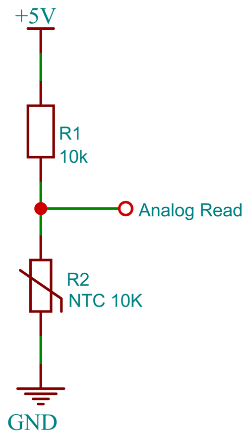
We shall be using resistance dividing network as shown where R2 is NTC thermistor value which keeps varying depending on temperature. R1 is constant resistor of 10k value so at 25 degree Centigrade both resistors are equal at 10k and Analog read or Vout will be 2.5 volts.
Vout = Vin*[R2/(R1+R2)] from this formula since we know all the parameters other than R2 we can quickly find out R2=(Vout*R1) / (Vin-Vout)
NTC and PTC Thermistors interfacing with Arduino and display on LCD
The break out board consists of 4 pins of which 2 are VCC and GND which are connected to 5 volts DC and ground terminals of Arduino. Other two pins are Aout and Dout which are connected to A0 Analog pin and Pin 7 Digital pin of Arduino. We have an LCD panel which displays live thermistor temperature using I2C interface.
Then we have two LEDs and a buzzer while Green LED is connected pin 2 to indicate power on condition, Red LED and Buzzer are used to draw the attention of the user if the temperature exceeds set value. Red LED is connected to pin 3 and buzzer is connected to pin 4 of arduino. The current limiting resistors of 220 ohms are connected to both LEDs and Buzzer in the ground curcuit and the common point is connected to ground.
NTC and PTC Thermistors interfacing with Node MCU and display on LCD
The break out board consists of 4 pins of which 2 are VCC and GND which are connected to 3.3 volts DC and ground terminals of Node MCU. Other two pins are Aout and Dout which are connected to ADC0 Analog pin and Pin GPIO7 Digital pin of Node MCU. We have an LCD panel which displays live thermistor temperature using I2C interface.
Then we have two LEDs and a buzzer while Green LED is connected pin GPIO2 to indicate power on condition, Red LED and Buzzer are used to draw the attention of the user if the temperature exceeds set value. Red LED is connected to pin GPIO3 and buzzer is connected to pin GPIO4 of arduino. The current limiting resistors of 220 ohms are connected to both LEDs and Buzzer in the ground curcuit and the common point is connected to ground.
NTC and PTC Thermistors interfacing with ESP32 and display on LCD
The break out board consists of 4 pins of which 2 are VCC and GND which are connected to 3.3 volts DC and ground terminals of ESP32. Other two pins are Aout and Dout which are connected to ADC0 Analog pin and Pin GPIO7 Digital pin of ESP32. We have an LCD panel which displays live thermistor temperature using I2C interface.
Then we have two LEDs and a buzzer while Green LED is connected pin GPIO2 to indicate power on condition, Red LED and Buzzer are used to draw the attention of the user if the temperature exceeds set value. Red LED is connected to pin GPIO3 and buzzer is connected to pin GPIO4 of arduino. The current limiting resistors of 220 ohms are connected to both LEDs and Buzzer in the ground curcuit and the common point is connected to ground.
