MAX6675 K-type Thermocouple Sensor interfaced
with Arduino, Node MCU, ESP32 with OLED display
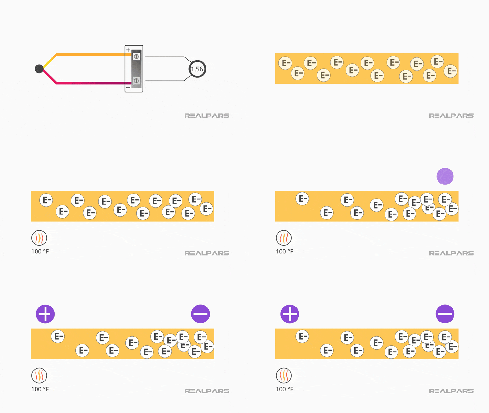
Thermoelectric effect
All thermocouples work the same way. They generate a small voltage when they are exposed to heat. When you heat up a piece of metal, the electrons in the metal want to move around more and will tend to move through the metal away from the heat. Because electrons are negatively charged, the colder end of the piece of metal will have a negative charge compared to the hotter end.
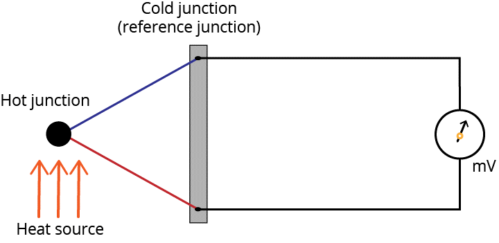
Thermocouple working:
A thermocouple works based on the movement of the electrons in its metal wires due to the heat difference between the hot and cold junctions. If the two wires of the thermocouple were made up of the same type of metal, electrons in both wires would move away from the heat at roughly the same rate, so you couldn’t really measure the difference in the charge of the two wires.
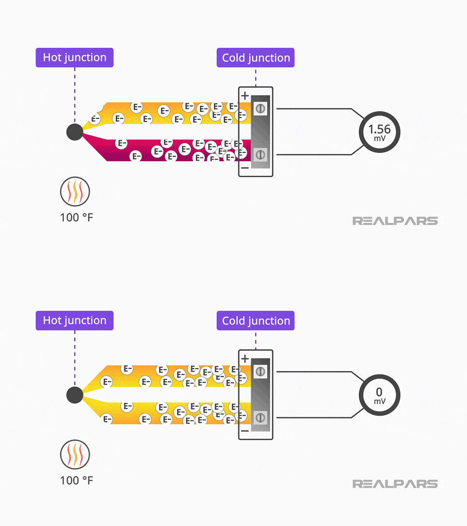
But if you recall, thermocouples are made up of two different types of metal wire… and those wires are connected together only at the hot junction… the sensing end of the thermocouple.
A thermocouple is a sensor for measuring temperature. This sensor consists of two dissimilar metal wires, joined at one end known as hot junction and when this junction is heated as per SeeBack effect there will be current flow between hot junction and the cold junction.
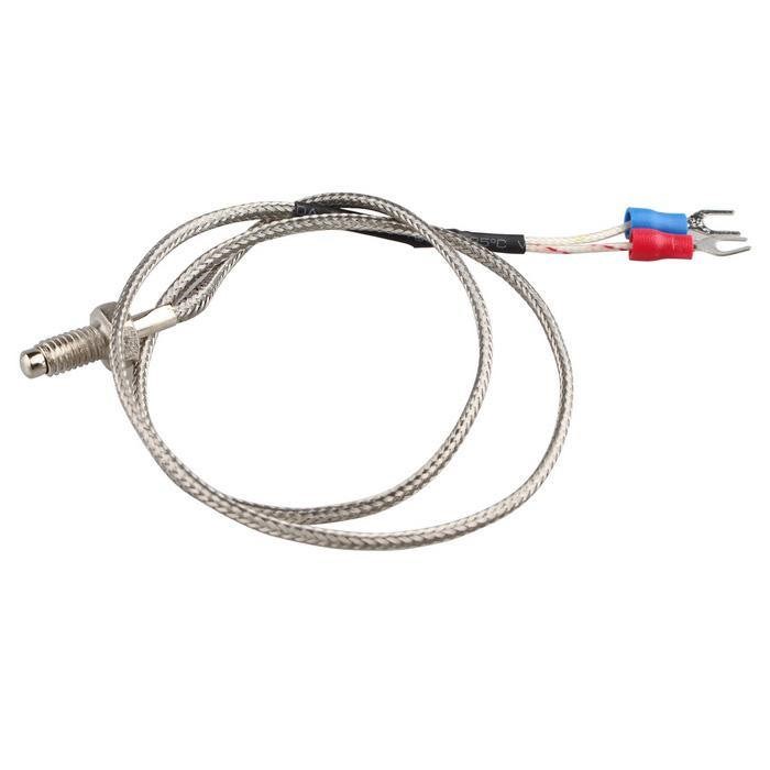
Thermocouples are known for their versatility as temperature sensors and there are different models to cover different temperature ranges and different shapes to meet different applications. Among all the different models K-type is most popular and covers the longest range in temperature measurement.
Type K thermocouples have a general temperature range of -200 to 1260°C (-326 to 2300°F), however there are some caveats to this: If used for temperatures below 0°C special material is needed in order to meet the specified accuracies. Also, Special Limits of Error are not specified for temperatures below 0°C.
A type K Thermocouple is made up of two dissimilar metals which are Nickel-Chromium / Nickel-Alumel. Type K is the most popular type of thermocouple because it is inexpensive, accurate, reliable (depending on the design used for your application) and covers a wide temperature range.
Type K thermocouples can be found in a broad range of applications due to its expansive temperature range capabilities. The maximum continuous temperature is up to around 1100°C. Thermocouples with a plug or cable can be identified by their colour coding. In this case type K is green. If you have a cable the green leg is positive and the white leg is negative.
However, the voltage generated is very small and for a large temperature variation there will be small voltage changes because of which we need to employ an amplifier before it being connected to ADC (Analog to Digital Converter) of micro-controller such as Arduino UNO.
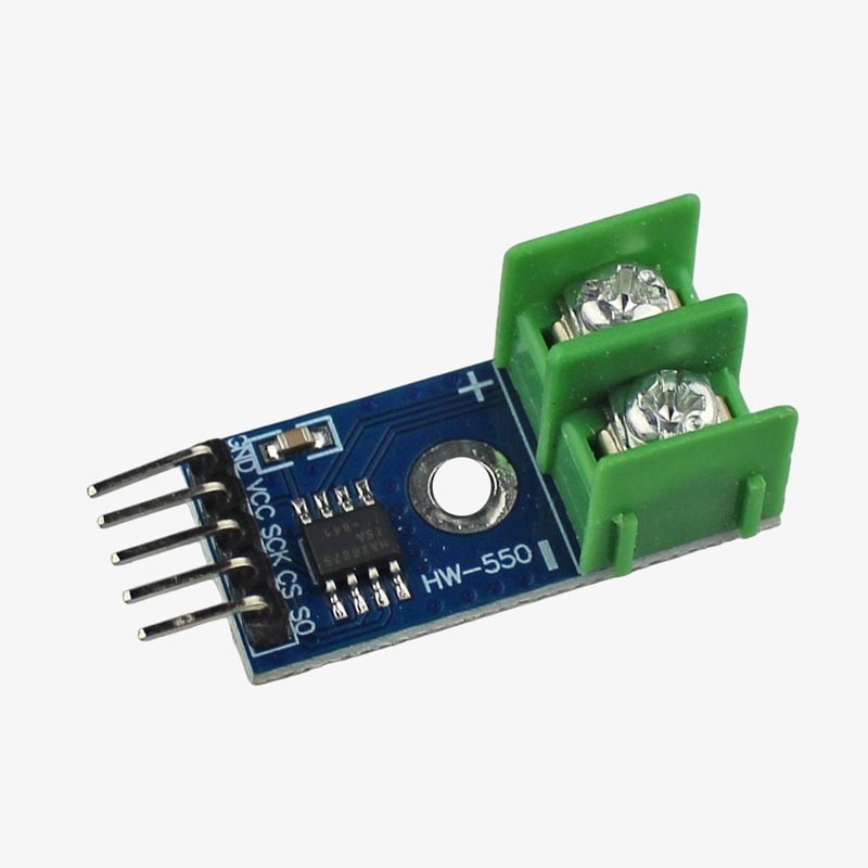
The MAX6675 is Thermocouple temperature sensor amplifier having linearity correction, thermocouple break detection and serial ADC output, its temperature resolution capability is 12bit i.e., 0.25 Degree accuracy, cold junction compensation range –20 ~ + 80 Degree (ambient temperature of the board on which the MAX6675 is mounted) using a temperature-sensing diode, wide operating voltage range 3.0 ~ 5.5V. There are 5 terminals for MAX6675 amplifier and they interface with micro controller on SPI bus. Then there is OLED which would display temperature is connected to Micro-controller on I2C bus.
MAX6675 K-type Thermocouple Sensor interfaced with Arduino:
VCC and GND are connected to 5 volts DC and ground of Arduino respectively. SCK (Clock), SO (Slave Out), CS (Chip Select) are connected to Arduino terminal 13, 11 and 10 of respectively. Apart from the above there are two LEDs and a buzzer which are connected to Arduino to give different signals. The green LED is connected to Pin 2 of Arduino which will switch on whenever the Arduino is powered up. The Red LED and Buzzer are connected to Pin 3 and Pin 4 of Arduino. The Red LED and buzzer would turn on whenever the temperature exceeds the set temperature.
MAX6675 K-type Thermocouple Sensor interfaced with Node MCU:
VCC and GND are connected to 3.3 volts DC and ground of Node MCU respectively. SCK (Clock), SO (Slave Out), CS (Chip Select) are connected to Node MCU terminal GPIO14, GPIO12 and GPIO15 respectively. Apart from the above there are two LEDs and a buzzer which are connected to Node MCU to give different signals. The green LED is connected to Pin GPIO2 of Node MCU which will switch on whenever the Node MCU is powered up. The Red LED and Buzzer are connected to Pin GPIO3 and Pin GPIO4 of Node MCU. The Red LED and buzzer would turn on whenever the temperature exceeds the set temperature
MAX6675 K-type Thermocouple Sensor interfaced with ESP32:
VCC and GND are connected to 3.3 volts DC and ground of Node MCU respectively. SCK (Clock), SO (Slave Out), CS (Chip Select) are connected to Node MCU terminal GPIO18, GPIO19 and GPIO5 respectively. Apart from the above there are two LEDs and a buzzer which are connected to Node MCU to give different signals. The green LED is connected to Pin GPIO2 of Node MCU which will switch on whenever the Node MCU is powered up. The Red LED and Buzzer are connected to Pin GPIO3 and Pin GPIO4 of Node MCU. The Red LED and buzzer would turn on whenever the temperature exceeds the set temperature.
