HTU21D Humidity and Temperature Sensor interfacing
with Arduino, Node MCU, ESP32 with OLED display
HTU21D is a low-cost, easy to use, highly accurate, digital humidity sensor. All you need is two lines for I2C communication and you’ll have relative humidity readings such as “45.2%” or “23.1%” and very accurate temperature readings as a bonus! HTU21D operates with I2C interface with Humidity accuracy of ±2% and temperature accuracy of ±0.3C.

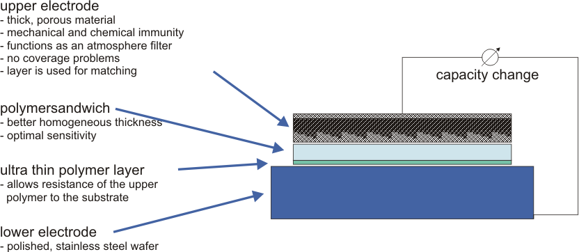
In principle capacitive sensors are based on the two electrodes (parallel metal plates) forming an electrical capacitor, whose capacitance changes reproducible with the humidity absorbed and deposited in a porous polymer contained between the capacitor’s plates. This capacitance change is amplified and converted to a digital signal by the ASIC connected to the electrodes. After an electronic calibration in the integrated Arithmetic unit digital data words for humidity and temperature can be read from HTU21D’s I2C output.
In addition to its capacitive sensing element HTU21X has a temperature sensor which is implemented by an integrated bandgap circuit. Information on the temperature is required in order to electronically compensate for the temperature in the sensor, allowing users to profit from the added benefit of an independent temperature sensor.

In automotive engineering HTU21X can be utilized to monitor humidity in electronic systems and in the vehicle interior to prevent windows from fogging over. There is an HTU21A automobile version for this particular application. Once car windows have steamed up, for instance, it is too late to clear them quickly with the fan. In most cases the driver has to wipe them with his or her hand which considerably limits his or her concentration on the traffic. In such cases help is provided by a fan controller which is based on the computation of the dew point temperature and reacts before car windows mist up
HTU21D Humidity and Temperature Sensor interfacing with Arduino:
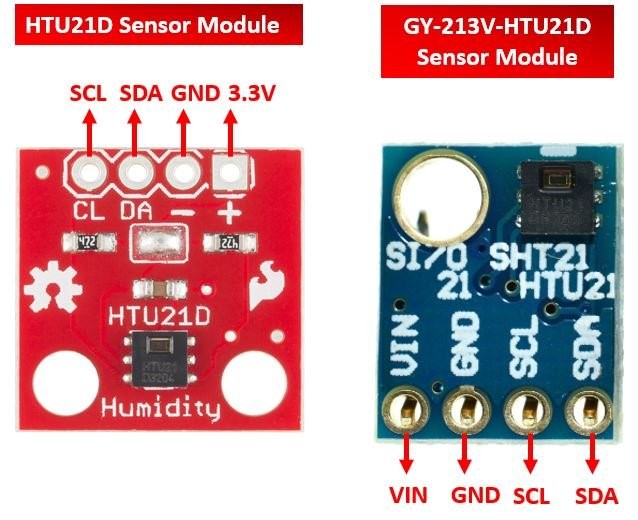
VIN and GND of the sensor module are connected to 5 volts DC and ground pin of the Arduino. SCL (Clock) and SDA (Data) of the sensor are connected to A5 and A4 of Arduino. Apart from this Pin 2, Pin 3 and Pin 4 are connected to Green LED, Red LED and Buzzer respectively. The Green LED indicates power on status of the Arduino, Red LED and Buzzer indicates either humidity or temperature exceeding the limits set. The information about humidity and temperature is displayed on OLED using I2C interface.
HTU21D Humidity and Temperature Sensor interfacing with Node MCU:
VIN and GND of the sensor module are connected to 3.3 volts DC and ground pin of the Node MCU. SCL (Clock) and SDA (Data) of the sensor are connected to GPIO5 and GPIO4 of Node MCU. Apart from this Pin GPIO2, Pin GPIO3 and Pin GPIO4 are connected to Green LED, Red LED and Buzzer respectively. The Green LED indicates power on status of the Node MCU, Red LED and Buzzer indicates either humidity or temperature exceeding the limits set. The information about humidity and temperature is displayed on OLED using I2C interface.
HTU21D Humidity and Temperature Sensor interfacing with ESP32:
VIN and GND of the sensor module are connected to 3.3 volts DC and ground pin of the ESP32. SCL (Clock) and SDA (Data) of the sensor are connected to GPIO22 and GPIO21 of ESP32. Apart from this Pin GPIO2, Pin GPIO3 and Pin GPIO4 are connected to Green LED, Red LED and Buzzer respectively. The Green LED indicates power on status of the ESP32, Red LED and Buzzer indicates either humidity or temperature exceeding the limits set. The information about humidity and temperature is displayed on OLED using I2C interface.
