2-Axis Joystick to control two servo motors
using Arduino, Node MCU, ESP32

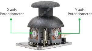
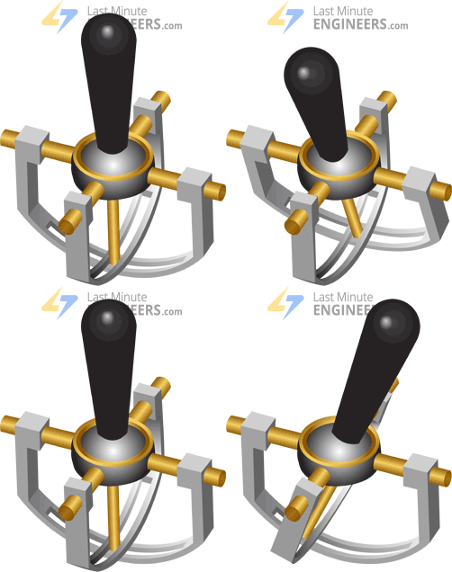
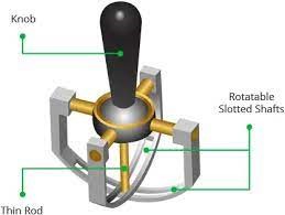
Potentiometers: The basic idea behind a joystick is to convert the stick’s position on two axes — the X-axis (left to right) and the Y-axis (up and down) — into an electrical signal that a microcontroller can process. This is accomplished by incorporating two 5K potentiometers (one for each axis) connected with a Gymbal mechanism that separates “horizontal” and “vertical” movements.
The two grey boxes on either side of the joystick are the potentiometers. If you move the joystick while keeping an eye on the potentiometer, you’ll notice that each potentiometer only detects movement in one direction. We’ll go over how they work in more detail later.
Momentary Pushbutton switch
This joystick also has a momentary pushbutton switch (a small black box on one side of the joystick) that is actuated when you press the joystick knob. When the knob is pressed down, you’ll notice a lever pressing down on the switch’s head. It is designed in such a way that the lever operates regardless of the position of the joystick.

The Joystick module is an Analog output device, which is used to sense movements in 2 directions (axis). It allows you to control X and Y directions. The Joystick module consists of two potentiometers and a push-button switch. These potentiometers provide Analog output values variable from 0 to 5 volts and the push button provides digital output value. It has a self-cantering spring-loaded mechanism; it means when we release the joystick knob/cap it will centre itself.

The joystick module consists of two 10k Potentiometers, one for X-axis, and one for Y-axis. Both potentiometers work independently providing 0 to 5 volts DC and when we connect DC motor or servo motor between each motor and ground we can control the speed of each motor independently.

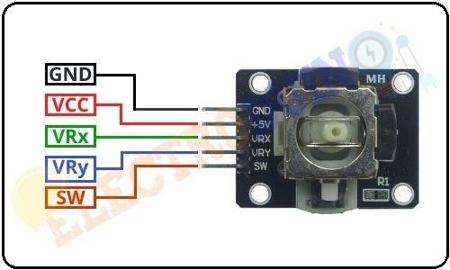
The joystick module consists of a Push Button Switch that activates when we press down the knob. Normally the digital output from the SW pin will be HIGH but when the button is pressed, it will connect to GND, giving output LOW.
According to the circuit diagram Potentiometer-VR1 represents X-axis and Potentiometer-VR2 represents Y-axis. The potentiometer is a variable resistor, when we will rotate the potentiometer knob the output voltage also changes at the signal pin. The joystick module knob is connected to these potentiometer knobs (VR1 & VR2). When we moved the joystick knob, the potentiometer knob also moves and output value changes. This way we can get the different Analog output values from the VRx and VRy pin of the module. So, this module provides Analog output in the range of 0-1023 (0v – 5v).
When the joystick module knob is in the centre position, the module outputs from both pins (VRx & VRy) is half of VCC means 2.5 volt, so the Analog output is approximately 512.
If the joystick knob is moved to the end of the +X-axis then the VRx pin output is 1023 (5v) and the VRy pin output is 512 (2.5v). If the joystick knob is moved to the end of the -X-axis then the VRx pin output is 0 (0v) and the VRy pin output is 512 (2.5v).

If the joystick knob is moved to the end of the +Y-axis then the VRy pin output is 1023 (5v) and the VRx pin output is 512 (2.5v). If the joystick knob is moved to the end of the -Y-axis then the VRy pin output is 0 (0v) and the VRx pin output is 512 (2.5v).

2-Axis Joystick to control two servo motors using Arduino:
There are 5 pins on the 2-axis joy stick. GND and VCC is connected to Ground and 5 volts DC of the Arduino. VRx and VRy are connected to +pins of each DC motor or servo motor. -pins of both motors are connected together to ground pin of Arduino. SW which is switch port of Joystick is connected internally to VCC. Then we have a Green LED, Red LED and Buzzer connected to Pin 2, Pin 3 and Pin 4 Arduino. Green LED lights up to indicate powering of Arduino. Red LED and Buzzer switches on whenever push button on joy stick (centre switch) is pressed.
2-Axis Joystick to control two servo motors using Node MCU:
There are 5 pins on the 2-axis joy stick. GND and VCC is connected to Ground and 3.3 volts DC of the Node MCU. VRx and VRy are connected to +pins of each DC motor or servo motor. -pins of both motors are connected together to ground pin of Node MCU. SW which is switch port of Joystick is connected internally to VCC. Then we have a Green LED, Red LED and Buzzer connected to Pin GPIO2, Pin GPIO3 and Pin GPIO4 Node MCU. Green LED lights up to indicate powering of Node MCU. Red LED and Buzzer switches on whenever push button on joy stick (centre switch) is pressed.
2-Axis Joystick to control two servo motors using ESP32:
There are 5 pins on the 2-axis joy stick. GND and VCC is connected to Ground and 3.3 volts DC of the ESP32. VRx and VRy are connected to +pins of each DC motor or servo motor. -pins of both motors are connected together to ground pin of ESP32. SW which is switch port of Joystick is connected internally to VCC. Then we have a Green LED, Red LED and Buzzer connected to Pin GPIO2, Pin GPIO3 and Pin GPIO4 ESP32. Green LED lights up to indicate powering of Node MCU. Red LED and Buzzer switches on whenever push button on joy stick (centre switch) is pressed.
