Magnetic Door Sensor with reed switch Interfacing
with Node MCU

The output of the voltage regulator is connected with the Vin pin of the Nodemcu ESP8266 Wifi module and the GND of the power supply is also connected with the ground of the Nodemcu Module.
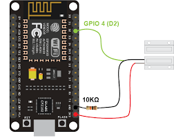
A magnetic Reed Switch is connected in series with a 10k resistor. This is a Pull Up resistor. When the two contacts of the Reed Switch are open it gives 3 volts to the digital pin D0 of the Nodemcu Module. On the other hand, when the two contacts of the Magnetic Reed Switch are closed, then GND is given as a signal to the digital pin D0 of the Nodemcu Module.

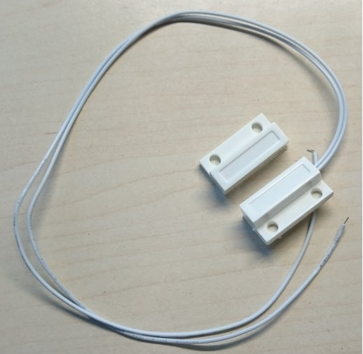
Normally the reed is ‘open’ (no connection between the two wires). The other half is a magnet. When the magnet is less than 13mm (0.5″) away, the reed switch closes and the contact is made between two wires. One part with wire is fitted on the frame of the door and is wired to Arduino. The other part viz., magnet is fixed on the door such that the distance between both elements is less than 13mm when the door is closed.
At present, door sensors are installed on the doors and windows for home security purposes. These sensors allow you to know once somebody has opened/closed a door. Many house owners utilize door sensors to guard entrances. However, these sensors work on any type of door. Actually, door sensors are so adaptable, so they are becoming very popular within activity triggers within smart home design. This article discusses an overview of a door sensor – working with applications
Blynk Application Designing for the IoT Door Sensor:
You can watch a video tutorial give at the end of this article or you can follow the following steps.
First of all, Open the Blynk application…
Click on the new project and enter the project name as IoT Door Security …
Click on the choose device and select Nodemcu…
Make sure you set the connection type to WIFI…
Finally, click on the create button, an authentication token will be sent on your email ID which will be then used in the programming. Simply copy and paste it in the programming…
Now click on the screen and search for the LED and add it…
Click again on the screen and add another LED…
Click again on the screen and this time search for the notification widget and add it…
Click on the first LED set the name as Door Open and select the virtual pin V2…
Now click on the 2nd LED to set the name as Door Close and select virtual pin V3…
That’s it. Our application is ready.
If door is found to be open and notification received the remote door locking Learn more
When door is opened notification to be sent through cloud Coming soon
When the door is opened relay should operate and switch on light Learn more
