How to interface LCD
with Arduino, Node MCU, ESP32 using I2C interface
The liquid-crystal display has the distinct advantage of having a low power consumption than the LED. It is typically of the order of microwatts for the display in comparison to the some order of milliwatts for LEDs. Low power consumption requirement has made it compatible with MOS integrated logic circuit. Its other advantages are its low cost, and good contrast. The main drawbacks of LCDs are additional requirement of light source, a limited temperature range of operation (between 0 and 60° C), low reliability, short operating life, poor visibility in low ambient lighting, slow speed and the need for an ac drive.
A liquid crystal cell consists of a thin layer (about 10 u m) of a liquid crystal sandwiched between two glass sheets with transparent electrodes deposited on their inside faces. With both glass sheets transparent, the cell is known as transmittive type cell. When one glass is transparent and the other has a reflective coating, the cell is called reflective type. The LCD does not produce any illumination of its own. It, in fact, depends entirely on illumination falling on it from an external source for its visual effect
Basic structure of an LCD
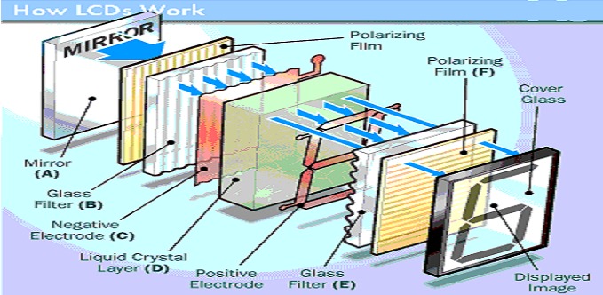
The main principle behind liquid crystal molecules is that when an electric current is applied to them, they tend to untwist. This causes a change in the light angle passing through them. This causes a change in the angle of the top polarizing filter with respect to it. So little light is allowed to pass through that particular area of LCD. Thus that area becomes darker comparing to others.
For making an LCD screen, a reflective mirror has to be setup in the back. An electrode plane made of indium-tin oxide is kept on top and a glass with a polarizing film is also added on the bottom side. The entire area of the LCD has to be covered by a common electrode and above it should be the liquid crystal substance. Next comes another piece of glass with an electrode in the shape of the rectangle on the bottom and, on top, another polarizing film. It must be noted that both of them are kept at right angles. When there is no current, the light passes through the front of the LCD it will be reflected by the mirror and bounced back.
As the electrode is connected to a temporary battery the current from it will cause the liquid crystals between the common-plane electrode and the electrode shaped like a rectangle to untwist. Thus the light is blocked from passing through. Thus that particular rectangular area appears blank.
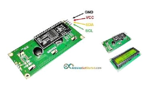
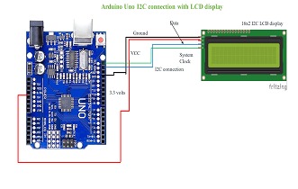
Arduino connection to LCD: LCD when coupled with I2C module will have only 4 terminals available for connection. VCC and GND are connected to 5 volts DC of Arduino and ground respectively. Then there are two more pins on I2C interface viz., SDA (Data) and SCL (Clock) terminals which shall be connected to SDA and SCL Pins of Arduino or they can be also connected to A5 and A4 Pins as well.
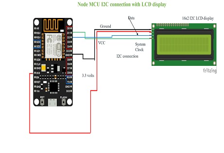
Node MCU connection to LCD: LCD when coupled with I2C module will have only 4 terminals available for connection. VCC and GND are connected to 5 volts DC of Node MCU (not 3.3 volts as minimum working voltage of LCD display is 4.7 volts) and ground respectively. Then there are two more pins on I2C interface viz., SDA (Data) and SCL (Clock) terminals which shall be connected to SDA GPIO4 Pin and SCL GPIO5 Pins of Node MCU.
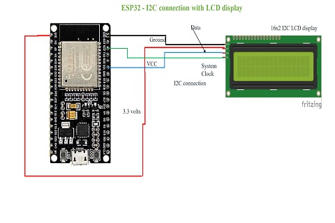
ESP32 connection to LCD: LCD when coupled with I2C module will have only 4 terminals available for connection. VCC and GND are connected to 5 volts DC of ESP32 (not 3.3 volts as minimum working voltage of LCD display is 4.7 volts) and ground respectively. Then there are two more pins on I2C interface viz., SDA (Data) and SCL (Clock) terminals which shall be connected to SDA GPIO21 and SCL GPIO22 Pins of ESP32.
