How to determine speed of the motor
with shaft mounted rotary encoder
Rotary encoders are a type of sensor that measures the rotation of a mechanical shaft. The shaft could be on a motor, where it would read the angular position or rotational speed. Encoders can also be used in control systems to provide feedback that a mechanical part is moving correctly in response to a control command. Based on the electrical outputs of the encoder, the direction of rotation, angular position, and rotational speed can be derived. The digital outputs of rotary encoders make this much simpler compared to potentiometers.

Optical encoders are built using a disc with translucent and opaque segments laid out to let light through certain areas. Using a LED and photodiodes on opposite sides of the disc (Figure 1), the photodiodes detect the light passing through the disc and output pulse waveforms corresponding to the translucent and opaque patterns on the segments of the disc. The absolute disc in Figure 1 has four outputs, providing a unique binary code for each segment on the disc — 16 in this case.
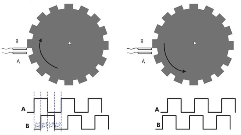
The pattern generated by the incremental disc consists of two square waves with a 90° phase difference and is referred to as a quadrature output. This can also be accomplished using a single row pattern and two photoelectric sensors displaced by a distance equivalent to the 90° phase shift. The outputs of quadrature incremental encoders are generally referred to as A and B. The encoder may also include a third once-per-revolution pulse, called an index pulse, to provide a known physical reference.
With the two quadrature signals, it is possible to resolve four states per cycle. The states within a single cycle are A = 1 and B = 0, A = 1 and B = 1, A = 0 and B = 1, and finally A = 0 and B = 0. This means that the angular resolution of a quadrature output encoder is four times that of the rated pulses per revolution (PPR).
The quadrature outputs of a 512 pulse-per-revolution (PPR) optical encoder showing the phase relationships between the A and B signal outputs.
Only the single A output was used in this example, as the encoder was applied as a tachometer, measuring the rotational speed of a motor. The frequency of the A signal is measured as 28.87 kilohertz (kHz) using the oscilloscope parameter P2. This is converted into the shaft speed by dividing by the 512 pulses per revolution (PPR) and multiplying by 60 to read the shaft angular speed in revolutions per minute (RPM), as read out in parameter P3 as 3383 RPM.
Optical encoders offer the benefit of having the highest resolution of all the encoder types. Their costs scale well to inexpensive, low-end applications. On the negative side, they can be bulky. Mechanical encoders use a rotating disc containing concentric rings identical to the patterns used in optical encoders. The rings have a pattern of conductive and insulated areas. Stationary wiper contacts slide over the rotating disc, making contact with each ring and acting as switches. As the contacts wipe across the surface of the disc, contact is made when wiping over a conductive region or broken when wiping over an insulated area. In this manner, a digital pattern is developed for each ring.
