Control Servo Motor using Rotary Encoder
with Arduino, Node MCU, ESP32 and Display on LCD
Control a servo motor with a rotary encoder using microcontroller and display the angle rotated on the LCD display. Interfacing a servo motor with rotary encoder with a Microcontroller is to achieve accurate control over a servo motor. controlling a servo motor using a rotary encoder with Arduino can be used in various practical applications like Robotic Arm Control, Camera Pan-Tilt Mechanism, Surveillance camera systems, Manual Solar Trackers, CNC Machine Control, Industrial Automation.
Servo motor is designed to provide precise control over angular rotation, making it ideal for applications requiring specific movements or positions. Servo motors consist of a DC motor, gears, and a control circuit. The control circuit receives a control signal, usually in the form of a pulse width modulation (PWM) signal, to determine the desired position of the motor shaft.
A rotary encoder is an electromechanical device used to convert angular position or rotation into digital or analog signals. It provides feedback on the rotational movement, enabling accurate measurement and control. Rotary encoders typically consist of a rotating disk, sensors (optical or magnetic), and output circuitry. As the encoder rotates, the sensors detect the changes in position, generating corresponding electrical signals.

Servo motors work on a closed-loop control system. The control signal sent to the servo motor determines the desired position. The internal control circuit compares the current position with the desired position and adjusts the motor’s rotation accordingly. This feedback loop ensures accurate positioning.
Rotary encoders, on the other hand, provide feedback on the rotational movement. The encoder generates electrical signals, such as pulses or digital codes, representing the direction and magnitude of rotation. By monitoring these signals, we can track the position, speed, and direction of the rotary encoder

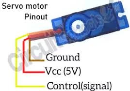
As you can see from the above circuit diagram Servo motor RED and BROWN wires which are positive and negative are connected to 5V and GND pins of Arduino respectively. The ORANGE wire which is for control is connected to Arduino digital pin 9.
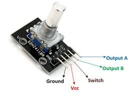
And next Rotary encoder power pins + and GND are connected to 5V and GND pins of Arduino respectively. And next CLK, DT and SW pins of Encoder are connected to digital pins 2,3 and 4 of Arduino respectively.
And finally we are connecting an LCD display module with I2C adapter which has only 4 pins. LCD display power pins VCC and GND are connected to 5V and GND of Arduino respectively and I2C pins SDA and SCL are connected to A4 and A5 respectively. That’s it for connection, next we need to write a program and upload it to Arduino.
